IRG4PC30F International Rectifier, IRG4PC30F Datasheet
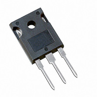
IGBT FAST 600V 31A TO-247AC

IRG4PC30F

Manufacturer Part Number
IRG4PC30F
Description
IGBT FAST 600V 31A TO-247AC
Manufacturer
International Rectifier
Datasheet

Specifications of IRG4PC30F

Voltage - Collector Emitter Breakdown (max)
600V
Vce(on) (max) @ Vge, Ic
1.8V @ 15V, 17A
Current - Collector (ic) (max)
31A
Power - Max
100W
Input Type
Standard
Mounting Type
Through Hole
Package / Case
TO-247-3 (Straight Leads), TO-247AC
Lead Free Status / RoHS Status
Contains lead / RoHS non-compliant
Igbt Type
-
Other names
*IRG4PC30F

Available stocks

Company
Part Number
Manufacturer
Quantity
Price
Part Number:
IRG4PC30F
Manufacturer:
IR
Quantity:
854
Part Number:
IRG4PC30F
Manufacturer:
IR
Quantity:
12 500
Part Number:
IRG4PC30FD
Manufacturer:
IR
Quantity:
12 500
Part Number:
IRG4PC30FPBF
Manufacturer:
International Rectifier
Quantity:
1 784
Part Number:
IRG4PC30FPBF
Manufacturer:
IR
Quantity:
20 000
Company:
Part Number:
IRG4PC30FPBF
Quantity:
9 003
Benefits
Absolute Maximum Ratings
Thermal Resistance
Features
Features
Features
Features
Features
• Generation 4 IGBT's offer highest efficiency available
• IGBT's optimized for specified application conditions
• Designed to be a "drop-in" replacement for equivalent
www.irf.com
• Fast: Optimized for medium operating
• Generation 4 IGBT design provides tighter
• Industry standard TO-247AC package
R
R
R
Wt
V
I
I
I
I
V
E
P
P
T
T
C
C
CM
LM
kHz in resonant mode).
Generation 3
parameter distribution and higher efficiency than
J
STG
CES
GE
ARV
D
D
industry-standard Generation 3 IR IGBT's
frequencies ( 1-5 kHz in hard switching, >20
JA
CS
JC
@ T
@ T
@ T
@ T
C
C
C
C
= 25°C
= 100°C
= 25°C
= 100°C
Junction-to-Case
Case-to-Sink, Flat, Greased Surface
Junction-to-Ambient, typical socket mount
Weight
Collector-to-Emitter Breakdown Voltage
Continuous Collector Current
Pulsed Collector Current Q
Clamped Inductive Load Current R
Gate-to-Emitter Voltage
Reverse Voltage Avalanche Energy S
Maximum Power Dissipation
Operating Junction and
Storage Temperature Range
Soldering Temperature, for 10 seconds
Mounting torque, 6-32 or M3 screw.
Parameter
Parameter
G
n-channel
300 (0.063 in. (1.6mm from case )
6 (0.21)
Typ.
0.24
–––
–––
E
C
10 lbf•in (1.1N•m)
-55 to + 150
TO-247AC
Max.
± 20
600
120
100
120
31
17
10
42
V
@V
CE(on) typ.
Max.
GE
V
–––
–––
1.2
40
CES
= 15V, I
= 600V
C
1.59V
= 17A
Units
g (oz)
Units
°C/W
mJ
W
°C
V
V
1229//00
A
1

Related parts for IRG4PC30F

IRG4PC30F Summary of contents

Page 1

Features Features Features Features Features • Fast: Optimized for medium operating frequencies ( 1-5 kHz in hard switching, >20 kHz in resonant mode). • Generation 4 IGBT design provides tighter parameter distribution and higher efficiency than Generation 3 • Industry ...

Page 2

Electrical Characteristics @ T Parameter V Collector-to-Emitter Breakdown Voltage (BR)CES Emitter-to-Collector Breakdown Voltage T V (BR)ECS Temperature Coeff. of Breakdown Voltage (BR)CES J V Collector-to-Emitter Saturation Voltage CE(ON) V Gate Threshold Voltage GE(th Temperature ...

Page 3

ted volta 0.1 Fig. 1 ...

Page 4

ase Tem perature (°C) C Fig Maximum Collector Current vs. Case Temperature ...

Page 5

MHz GE Cies = Cge + Cgc + Cce Cres = Cce Coes = Cce + Cgc ies ...

Page 6

150° 480V 15V G E 4.0 3.0 2.0 1.0 0 Collector-to-Emitter Current (A) C Fig Typical ...

Page 7

L 50V Driver .T 80 Note the 50V pow er s upply, pulse w idth ...

Page 8

(. (. ...

Page 9

Note: For the most current drawings please refer to the IR website at: http://www.irf.com/package/ ...

Related keywords