TFA9810T-T NXP Semiconductors, TFA9810T-T Datasheet
TFA9810T-T
Specifications of TFA9810T-T


Related parts for TFA9810T-T


TFA9810T-T Summary of contents
Page 1
TFA9810 Stereo full-bridge audio amplifi Rev. 03 — 20 February 2008 1. General description The TFA9810 is a two-channel power comparator for high-efficiency class D audio amplifier systems. It contains two full-bridge Bridge-Tied Load (BTL) power ...
Page 2
... NXP Semiconductors Table amb Symbol P o(RMS Ordering information Table 2. Ordering information Type number Package Name TFA9810T SO32 TFA9810_3 Product data sheet Quick reference data …continued = 550 kHz; Figure 33 P osc Parameter Condition RMS output power THD = 10 %; Two channel driven; no heat sink required ...
Page 3
... NXP Semiconductors 6. Block diagram TFA9810 V DDA1 4 IN1P 2 COMPARATOR 1 IN1N SSA1 10 DIAG PROTECTION OVP UVP OCP OTP ODP TEST 11 WP SO/OL 6 REFERENCE ENABLE 7 CDELAY DDA2 IN2P 15 COMPARATOR 2 IN2N SSA2 Fig 1. Block diagram TFA9810_3 Product data sheet DRIVER HIGH CONTROL LOGIC DRIVER LOW ...
Page 4
... NXP Semiconductors 7. Pinning information 7.1 Pinning Fig 2. The SO32 package has four corner leads. These leads (1, 16, 17, and 32) are internally connected to the die pad and must be connected to V the applied copper area on the Printed Circuit Board (PCB) these leads determine the ambient temperature, which affects the thermal resistance of the junction ...
Page 5
... NXP Semiconductors Table 3. Symbol IN2N IN2P STAB2 V SSP2 BOOT2N OUT2N BOOT2P OUT2P V DDP2 V DDP1 OUT1P BOOT1P OUT1N BOOT1N V SSP1 STAB1 8. Functional description 8.1 General The TFA9810 is a dual-switching power comparator the main building block for a stereo high-efficiency Class D audio power amplifier system. It contains two full-bridge ...
Page 6
... NXP Semiconductors In SLEEP mode the TFA9810 is not biased and has a very low supply current. When the TFA9810 is set to OPERATING mode the device is started via the start-up sequence, which provides a pop-free start-up behavior. After start-up the reference voltages STAB are present and the outputs start switching. ...
Page 7
... NXP Semiconductors • OverVoltage Protection (OVP) When the supply voltage applied to the TFA9810 exceeds the maximum supply voltage threshold level the device will shut down. The device will restart when the supply voltage is within the operating range. • UnderVoltage Protection (UVP) When the supply voltage applied to the TFA9810 falls below the minimum supply voltage threshold level the device will shut down ...
Page 8
... NXP Semiconductors 8.6 Start-up sequence V P ENABLE STAB1 CDELAY FLOATING OUT x AUDIO DIAG SLEEP START-UP Fig 3. Start-up sequence 9. Internal circuitry Fig 4. TFA9810_3 Product data sheet FLOATING PWM AUDIO OPERATING FAULT RESTART 1,16, 17, 32 Internal circuitry 0001 Rev. 03 — 20 February 2008 TFA9810 Audio amplifi ...
Page 9
... NXP Semiconductors Fig 5. Fig 6. Fig 7. TFA9810_3 Product data sheet 2 hvp 3 Internal circuitry 0002 4 5 Internal circuitry 0003 V DDA1 6 Internal circuitry 0004 Rev. 03 — 20 February 2008 Audio amplifi DDA1 135 k 5 SSA 135 k 5 SSA1 010aaa025 22 V 010aaa026 V DDA1 50 A 110 k ...
Page 10
... NXP Semiconductors Fig 8. Fig 9. Fig 10. Internal circuitry 0007 TFA9810_3 Product data sheet V DDA1 7 Internal circuitry 0005 V DDA1 8 Internal circuitry 0006 V DDA1 10 V SSA1 Rev. 03 — 20 February 2008 TFA9810 Audio amplifi 250 nA V SSA 010aaa028 2 nA 200 DISCHARGE V SSA1 010aaa029 V SSD 010aaa030 © ...
Page 11
... NXP Semiconductors Fig 11. Internal circuitry 0008 Fig 12. Internal circuitry 0009 Fig 13. Internal circuitry 0010 Fig 14. Internal circuitry 0011 TFA9810_3 Product data sheet V DDA1 130 k hvp V SSA2 130 DDA2 100 SSD 010aaa034 Rev. 03 — 20 February 2008 TFA9810 Audio amplifi SSA1 010aaa031 ...
Page 12
... NXP Semiconductors Fig 15. Internal circuitry 0012 Fig 16. Internal circuitry 0013 Fig 17. Internal circuitry 0014 Fig 18. Internal circuitry 0015 TFA9810_3 Product data sheet 24 23 010aaa035 OUT2N 010aaa036 V DDP2 21 V SSP2 010aaa037 OUT2P 010aaa038 Rev. 03 — 20 February 2008 TFA9810 Audio amplifi © NXP B.V. 2008. All rights reserved. ...
Page 13
... NXP Semiconductors Fig 19. Internal circuitry 0016 Fig 20. Internal circuitry 0017 Fig 21. Internal circuitry 0018 Fig 22. Internal circuitry 0019 TFA9810_3 Product data sheet V DDP2 23 V SSP2 010aaa039 25 23 010aaa040 V DDP1 26 V SSP1 010aaa041 Rev. 03 — 20 February 2008 TFA9810 Audio amplifi © NXP B.V. 2008. All rights reserved. ...
Page 14
... NXP Semiconductors Fig 23. Internal circuitry 0020 Fig 24. Internal circuitry 0021 Fig 25. Internal circuitry 0022 10. Limiting values Table 7. In accordance with the Absolute Maximum Rating System (IEC 60134). Symbol Parameter ORM stg T amb P max TFA9810_3 Product data sheet DDA1 31 V Limiting values ...
Page 15
... NXP Semiconductors Table 7. In accordance with the Absolute Maximum Rating System (IEC 60134). Symbol Parameter esd 11. Thermal characteristics Table 8. Characteristics Symbol Parameter R thermal resistance th(j-a) from junction to ambient thermal j-lead characterization parameter from junction to lead thermal j-top characterization parameter from junction to top of ...
Page 16
... NXP Semiconductors Table 9. Static characteristics 550 kHz; amb P osc Symbol Parameter I input current I SO/OL input V LOW-level input voltage IL V HIGH-level input voltage with respect STABI V voltage on pin STABI STABI Comparator full-differential input stage V equivalent input offset offset(i)(eq) voltage V common mode voltage ...
Page 17
... NXP Semiconductors Table 10. Dynamic characteristics amb P L Symbol Parameter t response time resp t minimum pulse width w(min) R drain-source on-state DSon resistance output power po efficiency [1] High-side and low-side power switch have the same series resistance. [2] Output power measured across the loudspeaker load. Output power is measured indirectly via R 12 ...
Page 18
... NXP Semiconductors Table 11. AC characteristics measured in typical application amb P L Symbol Parameter S/N signal-to-noise ratio SVRR supply voltage ripple rejection channel separation cs [1] Minimum value determined by R5, R10, R17, R22 equalling +1 % and R7, R14, R18, R20 equalling 1 %. 13. Quality specification In accordance with SNW-FQ-611-E, ‘if this type is used as an audio amplifier’. The number of the quality specifi ...
Page 19
... NXP Semiconductors P o (W) Fig 26. BTL output power as function of supply voltage: THD = 0 (W) Fig 27. BTL output power as function of supply voltage: THD = 14.2 Output current limiting The peak output current is internally limited above a level minimum. During normal operation the output current should not exceed this threshold level otherwise the output signal will be distorted ...
Page 20
... NXP Semiconductors • load resistance [ ]. L • R DSon • series resistance [ ]. s Example speaker in BTL configuration can be used supply voltage without running into current limiting. Current limiting (clipping) will avoid audio holes, but it causes a sound distortion similar to voltage clipping. 14.3 Speaker configuration and impedance For a fl ...
Page 21
... NXP Semiconductors Fig 29. Input configuration for single-ended input 14.6 Curves measured in a typical application G (dB) Fig 30. Gain as a function of frequency TFA9810_3 Product data sheet + IN1P AUDIO DSP IN1N +30 v +25 +20 (1) (2) +15 + 100 (1) OUT1 (2) OUT2 Rev. 03 — 20 February 2008 TFA9810 Audio amplifi ...
Page 22
... NXP Semiconductors THD+N Fig 31. Total harmonic distortion + noise as a function of frequency THD+N Fig 32. Total harmonic distortion as a function of output power 14.7 Typical application diagram TFA9810 The typical application diagram with the TFA9810 supplied from an asymmetrical supply is shown in TFA9810_3 Product data sheet ...
Page 23
C32 C33 220 F 100 100 nF GND GND OUT1 GND R5 100 R31 IN1P IN1 ...
Page 24
C32 C33 220 F 100 100 nF GND GND OUT1 GND R5 100 R31 IN1P IN1 ...
Page 25
... Jumper BEAD 0. 100 for 20 dB 200 for 0 PCB switch TFA9810T Snubber network: bill of materials Quantity Reference 4 C27, C28, C29, C30 470 pF R27, R28, R29, R30 Rev. 03 — 20 February 2008 Audio amplifi Description General purpose 85 C, diameter 8 mm ...
Page 26
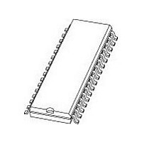
... NXP Semiconductors 16. Package outline SO32: plastic small outline package; 32 leads; body width 7 pin 1 index 1 e DIMENSIONS (inch dimensions are derived from the original mm dimensions) A UNIT max. 0.3 2.45 mm 2.65 0.25 0.1 2.25 0.012 0.096 inches 0.1 0.01 0.004 0.089 Note 1. Plastic or metal protrusions of 0.15 mm (0.006 inch) maximum per side are not included. ...
Page 27
... NXP Semiconductors 17. Revision history Table 15. Revision history Document ID Release date TFA9810_3 20080220 • Modifications: Figure 33 • Figure 34 TFA9810_2 20070831 TFA9810_1 20070815 TFA9810_3 Product data sheet Data sheet status Product data sheet has been updated. has been added. Preliminary data sheet Preliminary data sheet Rev. 03 — ...
Page 28
... Right to make changes — NXP Semiconductors reserves the right to make changes to information published in this document, including without limitation specifications and product descriptions, at any time and without notice ...
Page 29
... NXP Semiconductors 20. Contents 1 General description . . . . . . . . . . . . . . . . . . . . . . 1 2 Features . . . . . . . . . . . . . . . . . . . . . . . . . . . . . . . 1 3 Applications . . . . . . . . . . . . . . . . . . . . . . . . . . . . 1 4 Quick reference data . . . . . . . . . . . . . . . . . . . . . 1 5 Ordering information . . . . . . . . . . . . . . . . . . . . . 2 6 Block diagram . . . . . . . . . . . . . . . . . . . . . . . . . . 3 7 Pinning information . . . . . . . . . . . . . . . . . . . . . . 4 7.1 Pinning . . . . . . . . . . . . . . . . . . . . . . . . . . . . . . . 4 7.2 Pin description . . . . . . . . . . . . . . . . . . . . . . . . . 4 8 Functional description . . . . . . . . . . . . . . . . . . . 5 8.1 General . . . . . . . . . . . . . . . . . . . . . . . . . . . . . . . 5 8.2 Interfacing . . . . . . . . . . . . . . . . . . . . . . . . . . . . . 5 8.3 Input comparators 8.3.1 Operating in self-oscillating configuration . . . . . 6 8.3.2 Operating in open-loop confi ...