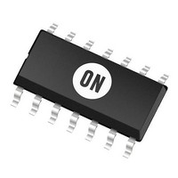
MC14541BD ON Semiconductor, MC14541BD Datasheet - Page 3

MC14541BD
Manufacturer Part Number
MC14541BD
Description
Timers & Support Products LOG CMOS OSILATR TIMER
Manufacturer
ON Semiconductor
Type
Programmabler
Datasheet
1.MC14541BD.pdf
(10 pages)
Specifications of MC14541BD
Number Of Internal Timers
1
Supply Voltage (max)
18 V
Supply Voltage (min)
3 V
Maximum Power Dissipation
500 mW
Maximum Operating Temperature
+ 125 C
Minimum Operating Temperature
- 55 C
Mounting Style
SMD/SMT
Propagation Delay (max)
18000 ns, 10000 ns, 7500 ns
Package / Case
SOIC-14
Lead Free Status / RoHS Status
Lead free / RoHS Compliant
Available stocks
Company
Part Number
Manufacturer
Quantity
Price
Part Number:
MC14541BDG
Manufacturer:
ON/安森美
Quantity:
20 000
Part Number:
MC14541BDR2
Manufacturer:
MOT
Quantity:
20 000
Company:
Part Number:
MC14541BDR2G
Manufacturer:
ON Semiconductor
Quantity:
7 400
Part Number:
MC14541BDR2G
Manufacturer:
ON/安森美
Quantity:
20 000
Î Î Î Î Î Î Î Î Î Î Î Î Î Î Î Î Î Î Î Î Î Î Î Î Î Î Î Î Î Î Î Î Î
Î Î Î Î Î Î Î Î Î Î Î Î Î Î Î Î Î Î Î Î Î Î Î Î Î Î Î Î Î Î Î Î Î
2. Data labelled “Typ” is not to be used for design purposes but is intended as an indication of the IC’s potential performance.
3. The formulas given are for the typical characteristics only at 25_C.
4. When using the on chip oscillator the total supply current (in mAdc) becomes: I
ELECTRICAL CHARACTERISTICS
Output Voltage
Input Voltage
Output Drive Current
Input Current
Input Capacitance
Quiescent Current
Auto Reset Disabled
Auto Reset Quiescent Current
Supply Current (Notes 3 & 4)
V
V
V
(V
(V
(V
(V
(V
(V
(V
(V
(V
(V
(V
(V
(V
(Pin 5 is High)
(Pin 5 is low)
(Dynamic plus Quiescent)
DD
in
in
O
O
O
O
O
O
OH
OH
OH
OL
OL
OL
in
= V
= 0 or V
in Volts DC, and f in kHz. (see Fig. 3) Dissipation during power−on with automatic reset enabled is typically 50 mA @ V
= 4.5 or 0.5 Vdc)
= 9.0 or 1.0 Vdc)
= 13.5 or 1.5 Vdc)
= 0.5 or 4.5 Vdc)
= 1.0 or 9.0 Vdc)
= 1.5 or 13.5 Vdc)
= 0)
= 0.4 Vdc)
= 0.5 Vdc)
= 1.5 Vdc)
= 2.5 Vdc)
= 9.5 Vdc)
= 13.5 Vdc)
Characteristic
DD
or 0
DD
“0” Level
“1” Level
“0” Level
“1” Level
Source
Sink
Symbol
I
V
V
V
I
I
DDR
V
I
C
(Voltages Referenced to V
OH
I
DD
I
OL
OH
OL
in
D
IH
IL
in
V
Vdc
5.0
5.0
5.0
5.0
5.0
5.0
5.0
5.0
10
15
10
15
10
15
10
15
10
15
10
15
15
10
15
10
15
10
15
DD
−
http://onsemi.com
– 4.19
– 7.96
– 16.3
14.95
4.95
9.95
1.93
4.96
19.3
Min
3.5
7.0
11
−
−
−
−
−
−
−
−
−
−
−
−
−
− 55_C
SS
3
± 0.1
)
Max
0.05
0.05
0.05
250
500
1.5
3.0
4.0
5.0
10
20
−
−
−
−
−
−
−
−
−
−
−
−
−
– 3.38
– 6.42
– 13.2
14.95
4.95
9.95
1.56
15.6
Min
3.5
7.0
4.0
11
I
I
I
T
−
−
−
−
−
−
−
−
−
−
−
−
−
D
D
D
= I
= (0.4 mA/kHz) f + I
= (0.8 mA/kHz) f + I
= (1.2 mA/kHz) f + I
D
+ 2 C
± 0.00001
(Note 2)
– 12.83
– 26.33
– 6.75
0.005
0.010
0.015
25_C
2.25
4.50
6.75
2.75
5.50
8.25
3.12
31.2
Typ
5.0
8.0
5.0
10
15
30
82
0
0
0
tc
V
DD
f x 10
± 0.1
Max
0.05
0.05
0.05
250
500
DD
DD
DD
1.5
3.0
4.0
7.5
5.0
10
20
−
−
−
−
−
−
−
−
−
−
−
−
–3
where I
– 2.37
– 4.49
− 9.24
14.95
4.95
9.95
1.09
10.9
Min
3.5
7.0
2.8
11
−
−
−
−
−
−
−
−
−
−
−
−
−
125_C
D
is in mA, C
± 1.0
1500
2000
Max
0.05
0.05
0.05
150
300
600
1.5
3.0
4.0
−
−
−
−
−
−
−
−
−
−
−
−
−
DD
= 10 Vdc.
tc
mAdc
mAdc
mAdc
mAdc
mAdc
mAdc
is in pF,
Unit
Vdc
Vdc
Vdc
Vdc
pF


