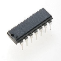
MC14541BCP ON Semiconductor, MC14541BCP Datasheet - Page 4

MC14541BCP
Manufacturer Part Number
MC14541BCP
Description
Timers & Support Products LOG CMOS OSILATR TIMER
Manufacturer
ON Semiconductor
Type
Programmabler
Datasheet
1.MC14541BD.pdf
(10 pages)
Specifications of MC14541BCP
Number Of Internal Timers
1
Supply Voltage (max)
18 V
Supply Voltage (min)
3 V
Maximum Power Dissipation
500 mW
Maximum Operating Temperature
+ 125 C
Minimum Operating Temperature
- 55 C
Mounting Style
Through Hole
Propagation Delay (max)
18000 ns, 10000 ns, 7500 ns
Package / Case
PDIP-14
Lead Free Status / RoHS Status
Lead free / RoHS Compliant
Available stocks
Company
Part Number
Manufacturer
Quantity
Price
Part Number:
MC14541BCP
Manufacturer:
ON/安森美
Quantity:
20 000
Company:
Part Number:
MC14541BCPG
Manufacturer:
IR
Quantity:
33 400
Part Number:
MC14541BCPG
Manufacturer:
ON/安森美
Quantity:
20 000
Î Î Î Î Î Î Î Î Î Î Î Î Î Î Î Î Î Î Î Î Î Î Î Î Î Î Î Î Î Î Î Î Î
Î Î Î Î Î Î Î Î Î Î Î Î Î Î Î Î Î Î Î Î Î Î Î Î Î Î Î Î Î Î Î Î Î
5. The formulas given are for the typical characteristics only at 25_C.
6. Data labelled “Typ” is not to be used for design purposes but is intended as an indication of the IC’s potential performance.
SWITCHING CHARACTERISTICS (Note 5)
Output Rise and Fall Time
Propagation Delay, Clock to Q (2
Propagation Delay, Clock to Q (2
Clock Pulse Width
Clock Pulse Frequency (50% Duty Cycle)
MR Pulse Width
Master Reset Removal Time
t
t
t
t
t
t
t
t
t
TLH
TLH
TLH
PLH
PLH
PLH
PHL
PHL
PHL
GENERATOR
Figure 1. Power Dissipation Test Circuit
PULSE
, t
, t
, t
, t
, t
, t
, t
, t
, t
20 ns
THL
THL
THL
PHL
PHL
PHL
PLH
PLH
PLH
(R
= (1.5 ns/pF) C
= (0.75 ns/pF) C
= (0.55 ns/pF) C
= (1.7 ns/pF) C
= (0.66 ns/pF) C
= (0.5 ns/pF) C
= (1.7 ns/pF) C
= (0.66 ns/pF) C
= (0.5 ns/pF) C
tc
AND C
10%
Characteristic
90% 50%
and Waveform
tc
R
AR
Q/Q SELECT
MODE
A
B
MR
OUTPUTS ARE LEFT OPEN)
S
DUTY CYCLE
L
L
L
L
L
L
L
L
L
+ 25 ns
V
+ 3415 ns
+ 875 ns
+ 5915 ns
+ 2475 ns
50%
+ 12.5 ns
+ 9.5 ns
DD
+ 1217 ns
+ 3467 ns
8
16
V
Output)
SS
Output)
20 ns
Q
C
L
(C
L
= 50 pF, T
http://onsemi.com
Symbol
t
t
WH(cl)
WH(R)
t
t
t
t
t
t
t
TLH
THL
PLH
PHL
PHL
PLH
A
rem
f
cl
= 25_C)
,
4
V
R
5.0
5.0
5.0
5.0
5.0
5.0
5.0
10
15
10
15
10
15
10
15
10
15
10
15
10
15
Q
DD
S
20 ns
GENERATOR
Figure 2. Switching Time Test Circuit
t
PLH
PULSE
t
TLH
50%
10%
Min
900
300
225
900
300
225
420
200
200
90% 50%
−
−
−
−
−
−
−
−
−
−
−
−
and Waveforms
10%
90%
(Note 6)
R
AR
Q/Q SELECT
MODE
A
B
MR
1.25
S
Typ
100
300
100
300
100
210
100
100
3.5
0.9
6.0
3.5
2.5
1.5
4.0
6.0
50
40
85
85
20 ns
V
DD
50%
V
SS
50%
Q
Max
10.5
0.75
200
100
3.8
2.9
7.5
2.0
3.0
80
18
10
−
−
−
−
−
−
−
−
−
t
PHL
C
t
THL
L
MHz
Unit
ns
ms
ms
ns
ns
ns


