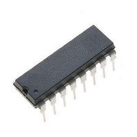
ML2021IP Fairchild Semiconductor, ML2021IP Datasheet - Page 7

ML2021IP
Manufacturer Part Number
ML2021IP
Description
Telecom Voice Conditioning ICs Phone Line Equalizer Group Delay Tuned
Manufacturer
Fairchild Semiconductor
Datasheet
1.ML2021IP.pdf
(11 pages)
Specifications of ML2021IP
Mounting Style
Through Hole
Package / Case
DIP-16
Lead Free Status / RoHS Status
Lead free / RoHS Compliant
Available stocks
Company
Part Number
Manufacturer
Quantity
Price
Company:
Part Number:
ML2021IP
Manufacturer:
ALCATEL
Quantity:
6 218
PRODUCT SPECIFICATION
Functional Description
The ML2021 consists of a continuous anti-alias filter, three
programmable switched capacitor equalization filters, an
output smoothing filter, an output driver, and a digital section
for the serial interface.
Anti-Alias Filter
The first section is a continuous anti-alias filter. This filter is
needed to prevent aliasing of high frequency signal present
on the input into the passband by the sampling action of the
switched capacitor filters. This section is a continuous sec-
ond order lowpass filter with a typical 3 dB frequency at 20
kHz and 30 dB of rejection at 124 kHz.
Equalization Filters
The programmable filters implement a family of frequency
response curves intended to compensate for the response of
telephone lines.
This filter is composed of three distinct sections: slope,
height, and bandwidth.
Response of Slope, Height, and Bandwidth
The family of response curves generated by the slope section
are shown in Figures 2 and 3. There are 4 slope select bits,
S3-S0. These bits alter the slope of the highpass response
under 1000Hz, and as a result, the absolute gain above 1000
Hz will be unique for each setting. Table 1 gives typical 1
kHz gain values for all slope settings.
Table 1. Typ. 1kHz Gain for Slope Settings
HT, BW Bits = 0
REV. 1.1.1 3/19/01
Slope
Setting
10
11
12
13
14
15
0
1
2
3
4
5
6
7
8
9
NL/L = 1
0.0
0.4
0.9
1.4
1.8
2.3
2.8
3.4
3.7
4.2
4.6
5.0
5.4
5.8
6.2
6.6
Rel 1kHz Gain (dB)
NL/L = 0
REL
10.0
10.5
11.0
11.4
1.4
2.6
3.7
4.7
5.5
6.3
7.2
7.8
8.4
9.0
9.5
There is an additional bit, NL/L, that also affects the high-
pass response of the slope filter. The slope response curves in
Figure 2 are with NL/L = 0. These same response curves are
shown in Figure 3 with NL/L = 1. Notice that the NL/L bit
adds more droop in the highpass response below 2500 Hz.
The family of response curves generated by the height sec-
tion are shown in Figure 4. There are 4 height select bits,
H3-H0. This section creates a peak in the response at 3250
Hz and this filter controls the amount of peaking. Table 2
gives typical 1 kHz gain values for all height and bandwidth
settings.
Table 2. Typ. 1kHz Gain for HT and BW Settings
Slope Bits = 0
The family of response curves generated by the bandwidth
section is shown in Figure 5. There are 4 bandwidth select
bits, B3-B0. This section causes the response of the 3250 Hz
peak to be widened, and as a result, this filter controls the
bandwidth of the 3250 Hz peaked region.
Transfer Function
The transfer function for the ML2021 is shown below. This
transfer function is valid for magnitude response only. The
actual magnitude response from an individual device may
deviate from the computed response from the transfer func-
tion by typically 0–0.2 dB.
s
ω
fc = 128000
b,c : See Table 3.
Q : See Table 4.
h
H s ( )
10
11
12
13
14
15
o
0
1
2
3
4
5
6
7
8
9
= j × 256000 × tan (πf/128000)
= 20463.77
: See Table 5.
Rel
0
0
0
0
0
0
0
0
0
0
0
0
0
0
0
0
=
c s
--------------------
b s
1
0
0
0
0
0
0
0
0
0
0
0
0
0
0
0
0
(
(
0.1
0.1
0.1
0.1
2
+
0
0
0
0
0
0
0
0
0
0
0
0
+
b
c
0.1
0.1
0.1
0.1
0.1
)
)
3
0
0
0
0
0
0
0
0
0
0
0
Relative 1kHz Gain (dB)
×
0.1
0.1
0.1
0.2
0.2
0.2
[
---------------------------------------------------------
4
0
0
0
0
0
0
0
0
0
0
[
s
s
2
2
+
0.1
0.1
0.1
0.2
0.3
0.3
0.3
5
+
0
0
0
0
0
0
0
0
0
HT Setting
h ω
(
(
ω
0.1
0.1
0.1
0.2
0.2
0.4
0.4
0.4
6
0
0
0
0
0
0
0
0
o
(slope)
(bandwidth)
(height)
o
⁄
0.1
0.1
0.1
0.2
0.3
0.5
0.5
0.5
⁄
7
0
0
0
0
0
0
0
0
Q
Q
)s
)s
0.1
0.1
0.1
0.2
0.3
0.4
0.6
0.7
0.7
8
0
0
0
0
0
0
0
+
+
0.1
0.1
0.2
0.3
0.4
0.5
0.8
0.8
0.9
ω
9 10 11 12 13 14 15
0
0
0
0
0
0
0
ω
o
o
2
2
0.1
0.1
0.1
0.2
0.3
0.4
0.7
0.9
1.0
1.1
]
0
0
0
0
0
0
]
×
0.1
0.1
0.2
0.3
0.4
0.5
0.8
1.1
1.2
1.3
0
0
0
0
0
0
[
-------------------------------
sin
(
0.1
0.1
0.1
0.2
0.3
0.5
0.7
1.0
1.4
1.5
1.6
0
0
0
0
0
πf fc
(
πf fc
⁄
0.1
0.1
0.2
0.3
0.4
0.6
0.8
1.1
1.6
1.7
1.8
0
0
0
0
0
⁄
ML2021
)
0.1
0.1
0.2
0.3
0.5
0.7
0.9
1.4
1.9
2.0
2.1
0
0
0
0
0
)
]
0.1
0.1
0.1
0.2
0.4
0.6
0.8
1.1
1.6
2.3
2.4
2.5
0
0
0
0
7


