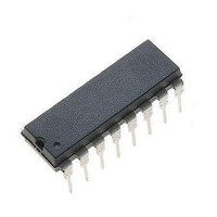
ETC5057N/H STMicroelectronics, ETC5057N/H Datasheet - Page 13

ETC5057N/H
Manufacturer Part Number
ETC5057N/H
Description
Telecom ICs Interfc CODEC Filter
Manufacturer
STMicroelectronics
Type
Telecom ICs - Variousr
Datasheet
1.ETC5054D-XHTR.pdf
(18 pages)
Specifications of ETC5057N/H
Operating Supply Voltage
7 V
Supply Current
10 uA
Operating Temperature Range
- 25 C to + 125 C
Mounting Style
Through Hole
Operating Frequency
2.048 MHz
Package / Case
PDIP-16
Lead Free Status / RoHS Status
Lead free / RoHS Compliant
Available stocks
Company
Part Number
Manufacturer
Quantity
Price
APPLICATION INFORMATION
POWER SUPPLIES
While the pins at the ETC505X family are well
protected against electrical misuse, it is recom-
mended that the standard CMOS practice be fol-
lowed, ensuring that ground is connected to the
device before any-other connections are made. In
applications where the printed circuit board may
be plugged into a "hot" socket with power and
clocks already present, an extra long ground pin
in the connector should be used.
All ground connections to each device should
meet at a common point as close as possible to
the GNDA pin. This minimizes the interaction of
ground return currents flowing through a common
bus impedance. 0.1 F supply decoupling capaci-
tors should be connected from this common
ground point to V
vice as possible.
For best performance, the ground point of each
CODEC/FILTER on a card should be connected
to a common card ground in star formation, rather
than via a ground bus. This common ground point
should be decoupled to V
capacitors.
Figure 4: T-PAD Attenuator
R1
R2
Where: N
and: S =
Also : Z = Z
Where Z
nation and Z
mination.
Figure 5: -PAD Attenuator
Z1
2 Z1.Z
SC
N
N
2
2
Z1
Z2
= impedance with short circuit termi-
OC
SC
2
1
1
POWEROUT
= impedance with open circuit ter-
.
POWERIN
N
Z
CC
OC
2
2 Z1 . Z 2
N
and V
1
CC
BB
and V
as close to the de-
N
2
N
BB
1
with 10 F
R3
R3
RECEIVE GAIN ADJUSTMENT
For
CODEC/filter receive output must drive a 600
load, but a peak swing lower then
quired, the receive gain can be easily adjusted by
inserting a matched T-pad or
put. Table II lists the required resistor values for
600
standard values, the equations can be used to
compute the attenuation of the closest pratical set
of resistors. It may be necessary to use unequal
values for the R1 or R4 arms of the attenuators to
achieve a precise attenuation. Generally it is tol-
erable to allow a small deviation of the input im-
pedance from nominal while still maintaining a
good return loss. For example a 30dB return loss
against 600
of the attenuator is in the range 282
(assuming a perfect transformer).
Table 2 : Attenuator Tables For
Z1 = Z2 = 300
0.1
0.2
0.3
0.4
0.5
0.6
0.7
0.8
0.9
1.0
dB
10
11
12
13
14
15
16
18
20
2
3
4
5
6
7
8
9
Z1
applications
terminations. As these are generally non-
Z1 .
N
2
2
Z
N
10.4
12.1
13.8
15.5
17.3
34.4
51.3
100
115
129
143
156
168
180
190
200
210
218
233
246
1.7
3.5
5.2
6.9
8.5
R1
68
84
2
is obtained if the output impedance
2
2NS
(all values in ).
N
1
2
N
where
1
1
8.7k
6.5k
5.2k
4.4k
3.7k
3.3k
2.9k
2.6k
1.3k
850
650
494
402
380
284
244
211
184
161
142
125
110
26k
13k
R2
98
77
61
ETC5054 - ETC5057
a
1.17k
ETC505X family
10.4
13.8
17.3
21.3
24.2
27.7
31.1
34.6
1.5k
–pad at the out-
107
144
183
224
269
317
370
427
490
550
635
720
816
924
3.5
6.9
R3
70
2.5V is re-
to 319
17.4k
10.5k
8.7k
7.5k
6.5k
5.8k
5.2k
2.6k
1.8k
1.3k
1.1k
900
785
698
630
527
535
500
473
450
430
413
386
366
52k
26k
13k
R4
13/18


