2SK3065T100 Rohm Semiconductor, 2SK3065T100 Datasheet
2SK3065T100
Specifications of 2SK3065T100
Available stocks


Related parts for 2SK3065T100


2SK3065T100 Summary of contents
Page 1
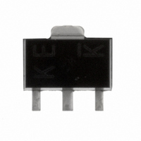
Transistors Small switching (60V, 2A) 2SK3065 !Features 1) Low on resistance. 2) High-speed switching. 3) Optimum for a pocket resource etc. because of undervoltage actuation (2.5V actuation). 4) Driving circuit is easy. 5) Easy to use parallel ...
Page 2
Transistors !Packaging specifications Package Taping Code T100 Type Basic ordering unit 1000 (pieces) 2SK3065 !Electrical characteristic curves 3 When mounted 0.7 mm aluminum-ceramic board 100 125 150 ...
Page 3
Transistors 10 V =2.5V GS Pulsed Ta=125°C 75°C 1 25°C −25°C 0.1 0.01 0.1 1 DRAIN CURRENT : Fig.7 Static Drain-Source On- State Resistance vs. Drain Current(ΙΙ =10V DS Pulsed Ta=−25°C 25°C 125°C 75°C ...
Page 4
Transistors 10 D=1 1 0.5 0.2 0.1 0.1 0.05 0.02 0.01 0.01 Single pulse 0.001 100µ 1m 10m 100m PULSE WIDTH : PW(s) Fig.16 Normarized Transient Thermal Resistance vs. Pulse Width !Switching characteristics measurement circuit ...