IRFIB5N65APBF Vishay, IRFIB5N65APBF Datasheet
IRFIB5N65APBF
Specifications of IRFIB5N65APBF
Available stocks


Related parts for IRFIB5N65APBF

IRFIB5N65APBF Summary of contents
Page 1
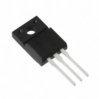
... STG Soldering Temperature, for 10 seconds Mounting torqe, 6- screw Typical SMPS Topologies Single Transistor Flyback l Single Transistor Forward l Notes through †are on page 8 Document Number: 91174 SMPS MOSFET IRFIB5N65APbF HEXFET V DSS 650V TO-220 Full-Pak @ 10V GS @ 10V GS - 150 300 (1.6mm from case ) 10 lbf•in (1.1N•m) PD-94837 ® ...
Page 2
... Intrinsic turn-on time is negligible (turn-on is dominated by L Conditions = 250µ 1mA† 3.1.A „ 250µ 0V 125° Conditions = 3.1A D „ = 1.0V, ƒ = 1.0MHz DS = 520V, ƒ = 1.0MHz 520V … DS Max. Units 325 mJ 5 Max. Units 2.1 65 °C/W Conditions „ = 5.2A 5. www.vishay.com 2 ...
Page 3
... Fig 4. Normalized On-Resistance VGS 15V 10V 8.0V 7.0V 6.0V 5.5V 5.0V 4.5V 4.5V 20µs PULSE WIDTH T = 150 C ° Drain-to-Source Voltage ( 10V 100 120 140 160 ° Junction Temperature ( C) J Vs. Temperature www.vishay.com 100 3 ...
Page 4
... Fig 8. Maximum Safe Operating Area 5. 520V 325V 130V DS FOR TEST CIRCUIT SEE FIGURE Total Gate Charge (nC) G Gate-to-Source Voltage OPERATION IN THIS AREA LIMITED BY R DS(on) 10us 100us 1ms 10ms ° ° = 150 C 100 1000 V , Drain-to-Source Voltage (V) DS www.vishay.com 13 50 10000 4 ...
Page 5
... Fig 11. Maximum Effective Transient Thermal Impedance, Junction-to-Case Document Number: 91174 Fig 10a. Switching Time Test Circuit V DS 90% 125 150 ° 10 d(on) Fig 10b. Switching Time Waveforms Notes: 1. Duty factor Peak 0.001 0. Rectangular Pulse Duration (sec ≤ 1 ≤ 0 d(off thJC C 0 www.vishay.com 5 ...
Page 6
... A 400 200 0 25 Starting T , Junction Temperature ( C) Fig 12c. Maximum Avalanche Energy 800 780 760 740 720 + 700 0 Fig 12d. Typical Drain-to-Source Voltage I D TOP 2.3A 3.3A BOTTOM 5. 100 125 ° J Vs. Drain Current Avalanche Current (A) av Vs. Avalanche Current www.vishay.com 150 ...
Page 7
... Voltage Inductor Curent Fig 14. For N-Channel HEXFET Document Number: 91174 + • • ƒ • - „ • • • • P.W. Period D = Period Body Diode Forward Current di/dt Diode Recovery dv/dt Body Diode Forward Drop Ripple ≤ 5% ® Power MOSFETs + - V =10V www.vishay.com 7 ...
Page 8
... Pulse width ≤ 300µs; duty cycle ≤ 2%. … C eff fixed capacitance that gives the same charging time oss as C while V is rising from 0 to 80% V oss DS † t=60s, f=60Hz , Data and specifications subject to change without notice COD DSS TAC Fax: (310) 252-7903 11/03 www.vishay.com 8 ...
Page 9
... Except as provided in Vishay's terms and conditions of sale for such products, Vishay assumes no liability whatsoever, and disclaims any express or implied warranty, relating to sale and/or use of Vishay products including liability or warranties relating to fitness for a particular purpose, merchantability, or infringement of any patent, copyright, or other intellectual property right. ...