IRFIB6N60A Vishay, IRFIB6N60A Datasheet

MOSFET N-CH 600V 5.5A TO220FP

IRFIB6N60A

Manufacturer Part Number
IRFIB6N60A
Description
MOSFET N-CH 600V 5.5A TO220FP
Manufacturer
Vishay
Series
HEXFET®r
Datasheet

Specifications of IRFIB6N60A

Fet Type
MOSFET N-Channel, Metal Oxide
Fet Feature
Standard
Rds On (max) @ Id, Vgs
750 mOhm @ 3.3A, 10V
Drain To Source Voltage (vdss)
600V
Current - Continuous Drain (id) @ 25° C
5.5A
Vgs(th) (max) @ Id
4V @ 250µA
Gate Charge (qg) @ Vgs
49nC @ 10V
Input Capacitance (ciss) @ Vds
1400pF @ 25V
Power - Max
60W
Mounting Type
Through Hole
Package / Case
TO-220-3 Full Pack (Straight Leads, Isolated), ITO-220AB
Configuration
Single
Transistor Polarity
N-Channel
Resistance Drain-source Rds (on)
0.75 Ohms
Drain-source Breakdown Voltage
600 V
Gate-source Breakdown Voltage
+/- 30 V
Continuous Drain Current
5.5 A
Power Dissipation
60 W
Maximum Operating Temperature
+ 150 C
Mounting Style
Through Hole
Minimum Operating Temperature
- 55 C
Lead Free Status / RoHS Status
Contains lead / RoHS non-compliant
Other names
*IRFIB6N60A

Available stocks

Company
Part Number
Manufacturer
Quantity
Price
Part Number:
IRFIB6N60A
Manufacturer:
IR
Quantity:
10 000
Part Number:
IRFIB6N60A
Manufacturer:
IR
Quantity:
12 500
Company:
Part Number:
IRFIB6N60APBF
Quantity:
7 150
Company:
Part Number:
IRFIB6N60APBF
Quantity:
70 000
l
l
l
l
l
l
l
l
l
www.irf.com
I
I
I
P
V
dv/dt
T
T
D
D
DM
J
STG
D
GS
Notes 
@ T
@ T
Drive Requirement
dv/dt Ruggedness
Avalanche Voltage and Current
@T
Single Transistor Forward
Switch Mode Power Supply ( SMPS )
Uninterruptable Power Supply
High speed power switching
High Voltage Isolation = 2.5KVRMS†
Low Gate Charge Qg results in Simple
Improved Gate, Avalanche and dynamic
Fully Characterized Capacitance and
Active Clamped Forward
C
C
C
= 25°C
= 100°C
= 25°C
through †are on page 8
Continuous Drain Current, V
Pulsed Drain Current 
Power Dissipation
Linear Derating Factor
Gate-to-Source Voltage
Peak Diode Recovery dv/dt ƒ
Operating Junction and
Storage Temperature Range
Soldering Temperature, for 10 seconds
Mounting torqe, 6-32 or M3 screw
Parameter
SMPS MOSFET
GS
GS
@ 10V
@ 10V
V
600V
DSS
300 (1.6mm from case )
TO-220 FULLPAK
HEXFET
10 lbf•in (1.1N•m)
-55 to + 150
Rds(on) max
Max.
0.48
± 30
5.5
3.5
5.0
37
60
0.75W
®
Power MOSFET
G
D
PD - 91813
S
Units
W/°C
5.5A
V/ns
°C
I
W
A
V
D
1
01/12/99

Related parts for IRFIB6N60A

IRFIB6N60A Summary of contents

Page 1

Switch Mode Power Supply ( SMPS ) Uninterruptable Power Supply l l High speed power switching High Voltage Isolation = 2.5KVRMS† l Low Gate Charge Qg results in Simple l Drive Requirement l Improved Gate, Avalanche and dynamic dv/dt ...

Page 2

Static @ T = 25°C (unless otherwise specified) J Parameter V Drain-to-Source Breakdown Voltage (BR)DSS R Static Drain-to-Source On-Resistance DS(on) V Gate Threshold Voltage GS(th) I Drain-to-Source Leakage Current DSS Gate-to-Source Forward Leakage I GSS Gate-to-Source Reverse Leakage Dynamic @ ...

Page 3

VGS TOP 15V 10V 8.0V 7.0V 6.0V 5.5V 5.0V BOTTOM 4. 20µs PULSE WIDTH 0.1 0 Drain-to-Source Voltage (V) DS Fig 1. Typical Output Characteristics 100 ° ...

Page 4

1MHz iss rss gd 2000 oss iss 1600 C oss 1200 800 C ...

Page 5

T , Case Temperature ( C) C Fig 9. Maximum Drain Current Vs. Case Temperature 0.50 1 0.20 0.10 0.05 0.1 0.02 0.01 SINGLE PULSE (THERMAL ...

Page 6

D.U 20V 0. Fig 12a. Unclamped Inductive Test Circuit Fig 12b. Unclamped Inductive Waveforms Charge Fig 13a. Basic Gate ...

Page 7

D.U.T + ‚ -  Driver Gate Drive P.W. D.U.T. I Waveform SD Reverse Recovery Current D.U.T. V Waveform DS Re-Applied Voltage Inductor Curent www.irf.com + · · ƒ · - „ · · · · P.W. Period ...

Page 8

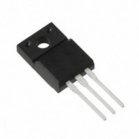
Package Outline TO-220 Fullpak Outline Dimensions are shown in millimeters (inches) 10.60 (.417) 10.40 (.409) 16.00 (.630) 15.80 (.622 13.70 (.540) 13.50 (.530) 1.40 (.055) 3X 1.05 (.042) 2.54 (.100) 2X EXAMPLE : THIS IS AN IRFI840G WITH ...

Related keywords