IRLR8103VTRLPBF International Rectifier, IRLR8103VTRLPBF Datasheet
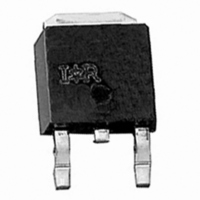
MOSFET N-CH 30V 91A DPAK

IRLR8103VTRLPBF

Manufacturer Part Number
IRLR8103VTRLPBF
Description
MOSFET N-CH 30V 91A DPAK
Manufacturer
International Rectifier
Series
HEXFET®r
Datasheet

Specifications of IRLR8103VTRLPBF

Fet Type
MOSFET N-Channel, Metal Oxide
Fet Feature
Logic Level Gate
Rds On (max) @ Id, Vgs
9 mOhm @ 15A, 10V
Drain To Source Voltage (vdss)
30V
Current - Continuous Drain (id) @ 25° C
91A
Vgs(th) (max) @ Id
3V @ 250µA
Gate Charge (qg) @ Vgs
27nC @ 5V
Input Capacitance (ciss) @ Vds
2672pF @ 16V
Power - Max
115W
Mounting Type
Surface Mount
Package / Case
DPak, TO-252 (2 leads+tab), SC-63
Transistor Polarity
N Channel
Continuous Drain Current Id
91A
Drain Source Voltage Vds
30V
On Resistance Rds(on)
9mohm
Rds(on) Test Voltage Vgs
10V
Peak Reflow Compatible (260 C)
Yes
Rohs Compliant
Yes
Configuration
Single
Resistance Drain-source Rds (on)
10.5 mOhms
Drain-source Breakdown Voltage
30 V
Gate-source Breakdown Voltage
20 V
Continuous Drain Current
89 A
Power Dissipation
89 W
Maximum Operating Temperature
+ 150 C
Mounting Style
SMD/SMT
Fall Time
18 ns
Gate Charge Qg
27 nC
Minimum Operating Temperature
- 55 C
Rise Time
9 ns
Lead Free Status / RoHS Status
Lead free / RoHS Compliant

Available stocks

Company
Part Number
Manufacturer
Quantity
Price
Part Number:
IRLR8103VTRLPBF
Manufacturer:
INTERNATIONAL RECTIFIER
Quantity:
30 000
www.irf.com
• N-Channel Application-Specific MOSFETs
• Ideal for CPU Core DC-DC Converters
• Low Conduction Losses
• Low Switching Losses
• Minimizes Parallel MOSFETs for high current
Description
This new device employs advanced HEXFET Power
MOSFET technology to achieve an unprecedented balance
of on-resistance and gate charge. The reduced conduction
and switching losses make it ideal for high efficiency DC-
DC converters that power the latest generation of
microprocessors.
The IRLR8103V has been optimized for all parameters
that are critical in synchronous buck converters including
R
The IRLR8103V offers an extremely low combination of
Q
synchronous FET applications.
The package is designed for vapor phase, infra-red,
convection, or wave soldering techniques. Power
dissipation of greater than 2W is possible in a typical PCB
mount application.
Absolute Maximum Ratings
Drain-Source Voltage
Gate-Source Voltage
Continuous Drain or Source Current
(V
Pulsed Drain Current
Power Dissipation
Junction & Storage Temperature Range
Continuous Source Current (Body Diode)
Pulsed Source Current
Thermal Resistance
Maximum Junction-to-Ambient
Maximum Junction-to-Case
DS(on)
sw
applications
100% R
Lead-Free
GS
& R
> 10V)
, gate charge and Cdv/dt-induced turn-on immunity.
DS(on)
G
Tested
for reduced losses in both control and
ÃÃÃÃÃÃÃÃÃÃÃÃÃ
Parameter
Parameter
h
h
TC = 25°C
TC = 25°C
TC = 90°C
TC= 90°C
T
Symbol
Symbol
J
R
R
V
V
I
, T
P
I
DM
I
I
SM
θJA
θJC
GS
D
DS
S
D
STG
DEVICE CHARACTERISTICS…
D-Pak
R
Q
Q
DS(on)
Q
OSS
IRLR8103VPbF
SW
G
Typ.
–––
–––
IRLR8103V
-55 to 150
±20
363
115
363
30
91
63
60
91
IRLR8103V
G
7.9 mΩ
27 nC
12 nC
29nC
Max.
1.09
50
PD - 95093A
Units
Units
°C/W
°C
W
D
S
V
A
A
1
12/0604

Related parts for IRLR8103VTRLPBF

IRLR8103VTRLPBF Summary of contents

Page 1

N-Channel Application-Specific MOSFETs • Ideal for CPU Core DC-DC Converters • Low Conduction Losses • Low Switching Losses • Minimizes Parallel MOSFETs for high current applications • 100% R Tested G • Lead-Free Description This new device employs advanced ...

Page 2

IRLR8103VPbF Electrical Characteristics Parameter Drain-to-Source Breakdown Voltage Static Drain-Source On-Resistance Gate Threshold Voltage Drain-to-Source Leakage Current Gate-Source Leakage Current Total Gate Charge, Control FET Total Gate Charge, Synch FET Pre-Vth Gate-Source Charge Post-Vth Gate-Source Charge Gate to Drain Charge Switch ...

Page 3

VGS TOP 15V 10V 7.0V 5.5V 4.5V 4.0V 3.5V BOTTOM 2.7V 100 2.7V 10 20µs PULSE WIDTH 0 Drain-to-Source Voltage (V) DS Fig 1. Typical Output Characteristics 1000 ° T ...

Page 4

IRLR8103VPbF 5000 1MHz iss rss 4000 oss ds gd 3000 C iss 2000 C oss 1000 C ...

Page 5

LIMITED BY PACKAGE 100 T , Case Temperature ( C) C Fig 9. Maximum Drain Current Vs. Case Temperature 0.50 0.20 0.10 0.1 0.05 SINGLE PULSE 0.02 ...

Page 6

IRLR8103VPbF 0.016 0.014 0.012 VGS = 4.5V 0.010 0.008 0.006 0 50 100 150 200 Drain Current ( A ) Fig 12. On-Resistance Vs. Drain Current Current Regulator Same Type as D.U.T. 50KΩ .2µF 12V .3µF V ...

Page 7

EXAMPLE: T HIS IS AN IRFR120 WITH AS S EMBLY LOT CODE 1234 AS S EMBLED ON WW 16, 1999 IN THE AS S EMBLY LINE "A" Note: "P" sembly line pos ition indicates "Lead-Free" OR www.irf.com INTERNATIONAL ...

Page 8

IRLR8103VPbF 12.1 ( .476 ) 11.9 ( .469 ) NOTES : 1. CONTROLLING DIMENSION : MILLIMETER. 2. ALL DIMENSIONS ARE SHOWN IN MILLIMETERS ( INCHES ). 3. OUTLINE CONFORMS TO EIA-481 & EIA-541. 13 INCH NOTES : 1. OUTLINE CONFORMS ...

Page 9

Note: For the most current drawings please refer to the IR website at: http://www.irf.com/package/ ...

Related keywords