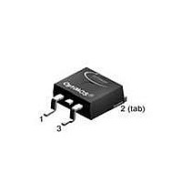
IPB200N25N3 G Infineon Technologies, IPB200N25N3 G Datasheet

IPB200N25N3 G
Specifications of IPB200N25N3 G
IPB200N25N3 GTR
Related parts for IPB200N25N3 G
IPB200N25N3 G Summary of contents
Page 1
... IPP200N25N3 G PG-TO220-3 200N25N Symbol Conditions I T =25 ° =100 ° =25 °C D,pulse = = =25 °C tot stg page 1 IPB200N25N3 G IPP200N25N3 G IPI200N25N3 G Product Summary DS(on),max I D IPI200N25N3 G PG-TO262-3 200N25N Value 64 46 256 320 ±20 300 -55 ... 175 55/175/56 250 Unit °C 2010-10-19 ...
Page 2
... =270 µA GS(th =200 DSS T =25 ° =200 =125 ° = GSS = =64 A DS(on |>2 DS(on)max = (one layer, 70 µm thick) copper area for drain page 2 IPB200N25N3 G IPP200N25N3 G IPI200N25N3 G Values min. typ. max 0 250 - 0 100 = 100 - 17 2 122 Unit K µ 2010-10-19 ...
Page 3
... Gate charge total Gate plateau voltage Output charge Reverse Diode Diode continous forward current Diode pulse current Diode forward voltage Reverse recovery time Reverse recovery charge 4) See figure 16 for gate charge parameter definition Rev. 2.3 IPB200N25N3 G Symbol Conditions C iss =100 oss f =1 MHz ...
Page 4
... Safe operating area I =f =25 ° parameter Rev. 2.3 2 Drain current I =f 150 200 4 Max. transient thermal impedance Z =f(t thJC parameter µs 10 µs 100 µ [V] page 4 IPB200N25N3 G IPP200N25N3 G IPI200N25N3 100 T [° 0.5 0.2 0.1 0.05 0.02 0.01 single pulse - [s] p 150 200 - 2010-10-19 ...
Page 5
... DS(on)max parameter 140 120 100 175 ° Rev. 2.3 6 Typ. drain-source on resistance R =f(I DS(on) parameter 4 [V] 8 Typ. forward transconductance g =f 180 160 140 120 100 ° [V] page 5 IPB200N25N3 G IPP200N25N3 G IPI200N25N3 =25 ° 4 100 I [ =25 ° [ 120 140 100 125 2010-10-19 ...
Page 6
... GS(th) parameter 3.5 3 2.5 2 1.5 typ 1 0.5 0 100 140 180 12 Forward characteristics of reverse diode I =f parameter Ciss 120 160 [V] page 6 IPB200N25N3 G IPP200N25N3 G IPI200N25N3 2700 µA 270 µA -60 - 100 T [° 175 °C 25°C, 98% 175°C, 98% 25 ° [V] SD 140 180 1.5 ...
Page 7
... Avalanche characteristics parameter: T j(start) 15 Drain-source breakdown voltage V =f BR(DSS 290 280 270 260 250 240 230 220 -60 - [°C] j IPB200N25N3 G 14 Typ. gate charge V =f gate parameter Gate charge waveforms 100 140 180 IPP200N25N3 G IPI200N25N3 G =25 A pulsed D DD 200 V 125 [nC] gate ...
Page 8
... PG-TO220-3: Outline Rev. 2.3 IPB200N25N3 G page 8 IPP200N25N3 G IPI200N25N3 G 2010-10-19 ...
Page 9
... PG-TO263-3: Outline Rev. 2.3 IPB200N25N3 G page 9 IPP200N25N3 G IPI200N25N3 G 2010-10-19 ...
Page 10
... PG-TO262-3: Outline Rev. 2.3 IPB200N25N3 G page 10 IPP200N25N3 G IPI200N25N3 G 2010-10-19 ...
Page 11
... Rev. 2.3 IPB200N25N3 G page 11 IPP200N25N3 G IPI200N25N3 G 2010-10-19 ...


