IRF7807 International Rectifier, IRF7807 Datasheet
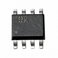
MOSFET N-CH 30V 8.3A 8-SOIC

IRF7807

Manufacturer Part Number
IRF7807
Description
MOSFET N-CH 30V 8.3A 8-SOIC
Manufacturer
International Rectifier
Series
HEXFET®r
Datasheet

Specifications of IRF7807

Fet Type
MOSFET N-Channel, Metal Oxide
Fet Feature
Standard
Rds On (max) @ Id, Vgs
25 mOhm @ 7A, 4.5V
Drain To Source Voltage (vdss)
30V
Current - Continuous Drain (id) @ 25° C
8.3A
Vgs(th) (max) @ Id
1V @ 250µA
Gate Charge (qg) @ Vgs
17nC @ 5V
Power - Max
2.5W
Mounting Type
Surface Mount
Package / Case
8-SOIC (3.9mm Width)
Lead Free Status / RoHS Status
Contains lead / RoHS non-compliant

Available stocks

Company
Part Number
Manufacturer
Quantity
Price
Part Number:
IRF7807
Manufacturer:
HAR
Quantity:
831
Part Number:
IRF7807
Manufacturer:
IOR
Quantity:
726
Part Number:
IRF7807
Manufacturer:
IR
Quantity:
20 000
Part Number:
IRF7807 TR
Manufacturer:
IRЕМЧ°
Quantity:
831
Part Number:
IRF7807A
Manufacturer:
IR
Quantity:
20 000
Part Number:
IRF7807ATRPBF
Manufacturer:
NXP
Quantity:
120 000
Part Number:
IRF7807ATRPBF
Manufacturer:
IR
Quantity:
20 000
Part Number:
IRF7807D1TR
Quantity:
1 700
Part Number:
IRF7807D2TRPBF
Manufacturer:
IR
Quantity:
20 000
Part Number:
IRF7807PBF
Manufacturer:
INF
Quantity:
4 534
Part Number:
IRF7807PBF
Quantity:
3 322
Part Number:
IRF7807TR
Manufacturer:
IOR
Quantity:
1 057
Part Number:
IRF7807TR
Manufacturer:
IOR
Quantity:
2 593
Part Number:
IRF7807TR
Manufacturer:
IOR
Quantity:
4 000
Part Number:
IRF7807TR
Manufacturer:
IR
Quantity:
20 000
Company:
Part Number:
IRF7807TR
Quantity:
1 370
Company:
Part Number:
IRF7807TRPBF
Quantity:
9 000
Company:
Part Number:
IRF7807TRPBF
Quantity:
3 932
• N Channel Application Specific MOSFETs
• Ideal for Mobile DC-DC Converters
• Low Conduction Losses
• Low Switching Losses
Description
These new devices employ advanced HEXFET Power
MOSFET technology to achieve an unprecedented
balance of on-resistance and gate charge. The
reduced conduction and switching losses make them
ideal for high efficiency DC-DC Converters that power
the latest generation of mobile microprocessors.
A pair of IRF7807 devices provides the best cost/
performance solution for system voltages, such as 3.3V
and 5V.
Absolute Maximum Ratings
Thermal Resistance
Parameter
Drain-Source Voltage
Gate-Source Voltage
Continuous Drain or Source
Current (V
Pulsed Drain Current
Power Dissipation
Junction & Storage Temperature Range
Continuous Source Current (Body Diode)
Pulsed source Current
Parameter
Maximum Junction-to-Ambientƒ
www.irf.com
GS
4.5V)
25°C
70°C
25°C
70°C
Symbol
T
HEXFET
J
R
V
V
, T
I
P
I
I
DM
I
SM
DS
GS
D
S
D
JA
STG
®
Chip-Set for DC-DC Converters
IRF7807
IRF7807/IRF7807A
2.5
8.3
6.6
SO-8
66
66
Vds
Rds(on)
Qg
Qsw
Qoss
–55 to 150
Device Features
Max.
±12
2.5
1.6
30
50
IRF7807 IRF7807A
16.8nC
5.2nC
25m
17nC
IRF7807A
30V
2.5
8.3
6.6
66
66
G
S
S
S
16.8nC
25m
1
2
3
4
17nC
T o p V ie w
30V
PD – 91747C
Units
Units
°C/W
°C
W
V
A
A
8
7
6
5
D
D
D
D
A
10/10/00
1

Related parts for IRF7807

IRF7807 Summary of contents

Page 1

... The reduced conduction and switching losses make them ideal for high efficiency DC-DC Converters that power the latest generation of mobile microprocessors. A pair of IRF7807 devices provides the best cost/ performance solution for system voltages, such as 3.3V and 5V. Absolute Maximum Ratings ...

Page 2

... Repetitive rating; pulse width limited by max. junction temperature. ‚ Pulse width 300 µs; duty cycle ƒ When mounted on 1 inch square copper board, t < 10 sec. „ Typ = measured - Q * Devices are 100% tested to these parameters. 2 IRF7807 IRF7807A Min Typ Max Min Typ Max Units 30 – – 30 – – ...

Page 3

... C and C when multiplied by the power ds dg supply input buss voltage. www.irf.com IRF7807/IRF7807A of the MOSFET GTH output Figure 1: Typical MOSFET switching waveform Synchronous FET The power loss equation for Q2 is approximated Q by ...

Page 4

... Vin = 14V 85 Vin = 24V 84 1 1.5 2 2.5 3 Load Current (A) Figure im- the MOSFET on, resulting in shoot-through current . ds(on) The ratio of Q potential for Cdv/dt turn on. Spice model for IRF7807 can be downloaded in ma- chine readable format at www.irf.com. and re- oss Figure 2: Q oss 3 ...

Page 5

... IRF7807 Figure 5. Normalized On-Resistance vs. Temperature Figure 7. Typical Gate Charge vs. Gate-to-Source Voltage Figure 9. Typical Rds(on) vs. Gate-to-Source Voltage www.irf.com IRF7807/IRF7807A Typical Characteristics Figure 6. Normalized On-Resistance vs. Temperature Figure 8. Typical Gate Charge vs. Gate-to-Source Voltage Figure 10. Typical Rds(on) vs. Gate-to-Source Voltage IRF7807A 5 ...

Page 6

... Figure 13. Maximum Effective Transient Thermal Impedance, Junction-to-Ambient 150 C 1 ° 0.1 0.8 0.9 0.4 Figure 12. Typical Source-Drain Diode Forward Voltage Notes: 1. Duty factor Peak 0 Rectangular Pulse Duration (sec) 1 IRF7807A ° J ° 0.5 0.6 0.7 0.8 0.9 V ,Source-to-Drain Voltage ( ...

Page 7

... Package Outline SO-8 Outline Part Marking Information SO-8 www.irf.com IRF7807/IRF7807A 7 ...

Page 8

... IRF7807/IRF7807A Tape & Reel Information SO-8 Dimensions are shown in millimeters (inches . . ( & LIN -48 1 & - WORLD HEADQUARTERS: 233 Kansas St., El Segundo, California 90245, USA Tel: (310) 252-7105 IR EUROPEAN REGIONAL CENTRE: 439/445 Godstone Rd, Whyteleafe, Surrey CR3 OBL, UK Tel (0)20 8645 8000 IR JAPAN: K&H Bldg., 2F, 30-4 Nishi-Ikebukuro 3-Chome, Toshima-Ku, Tokyo 171 Tel: 81 (0)3 3983 0086 IR SOUTHEAST ASIA: 1 Kim Seng Promenade, Great World City West Tower, 13-11, Singapore 237994 Tel (0)838 4630 IR TAIWAN:16 Fl ...

Related keywords