IRF7807VD1TR International Rectifier, IRF7807VD1TR Datasheet
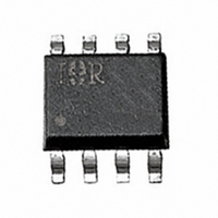
MOSFET N-CH 30V 8.3A 8-SOIC

IRF7807VD1TR

Manufacturer Part Number
IRF7807VD1TR
Description
MOSFET N-CH 30V 8.3A 8-SOIC
Manufacturer
International Rectifier
Series
FETKY™r
Datasheet

Specifications of IRF7807VD1TR

Fet Type
MOSFET N-Channel, Metal Oxide
Fet Feature
Diode (Isolated)
Rds On (max) @ Id, Vgs
25 mOhm @ 7A, 4.5V
Drain To Source Voltage (vdss)
30V
Current - Continuous Drain (id) @ 25° C
8.3A
Vgs(th) (max) @ Id
3V @ 250µA
Gate Charge (qg) @ Vgs
14nC @ 4.5V
Power - Max
2.5W
Mounting Type
Surface Mount
Package / Case
8-SOIC (3.9mm Width)
Lead Free Status / RoHS Status
Contains lead / RoHS non-compliant
Description
The FETKY
Schottky diodes offers the designer an innovative, board
space saving solution for switching regulator and power
management applications. HEXFET power MOSFETs
utilize advanced processing techniques to achieve
extremely low on-resistance per silicon area. Combining
this technology with International Rectifier’s low forward
drop Schottky rectifiers results in an extremely efficient
device suitable for use in a wide variety of portable
electronics applications.
The SO-8 has been modified through a customized
leadframe for enhanced thermal characteristics. The SO-
8 package is designed for vapor phase, infrared or wave
soldering techniques.
• Co-Pack N-channel HEXFET
• Ideal for Synchronous Rectifiers in DC-DC
• Low Conduction Losses
• Low Switching Losses
• Low Vf Schottky Rectifier
• 100% R
www.irf.com
Absolute Maximum Ratings
Drain-to-Source Voltage
Gate-to-Source Voltage
Continuous Output Current
(V
Pulsed Drain Current
Power Dissipation
Schottky and Body Diode
Average Forward Current
Junction & Storage Temperature Range
Thermal Resistance
Maximum Junction-to-Ambient
Maximum Junction-to-Lead
and Schottky Diode
Converters Up to 5A Output
GS
≥ 4.5V)
G
Tested
family of Co-Pack HEXFET
Parameter
Parameter
eÃÃÃÃÃÃÃÃÃÃÃ
f
h
eÃh
Power MOSFET
MOSFETs and
25°C
70°C
25°C
70°C
25°C
70°C
FETKY™ MOSFET / SCHOTTKY DIODE
T
Symbol
Symbol
I
J
F
R
R
V
V
I
, T
P
(AV)
I
DM
GS
θJA
θJL
DS
D
D
STG
SO-8
DEVICE CHARACTERISTICS…
R
Q
Q
Q
DS
G
sw
oss
(on)
Typ
–––
–––
-55 to 150
IRF7807VD1
Max
±20
8.3
6.6
2.5
1.6
3.5
2.2
IRF7807VD1
30
66
17mΩ
9.5nC
3.4nC
A/S
A/S
A/S
12nC
G
Max
50
20
1
2
3
4
Top View
PD-94078A
Units
Units
°C/W
8
6
5
7
°C
W
V
A
K/D
K/D
K/D
K/D
D
11/12/03
1

Related parts for IRF7807VD1TR

IRF7807VD1TR Summary of contents

Page 1

... HEXFET power MOSFETs utilize advanced processing techniques to achieve extremely low on-resistance per silicon area. Combining this technology with International Rectifier’s low forward drop Schottky rectifiers results in an extremely efficient device suitable for use in a wide variety of portable electronics applications. ...

Page 2

IRF7807VD1 Electrical Characteristics Parameter Drain-Source Breakdown Voltage Static Drain-Source On-Resistance Gate Threshold Voltage Drain-Source Leakage Current Gate-Source Leakage Current Total Gate Charge* Pre-Vth Gate-Source Charge Post-Vth Gate-Source Charge Gate-to-Drain Charge Switch Charge ( gs2 gd Output Charge* ...

Page 3

Power MOSFET Selection for DC/DC Converters Control FET Special attention has been given to the power losses in the switching elements of the circuit - Q1 and Q2. Power losses in the high side switch Q1, also called the Control ...

Page 4

IRF7807VD1 For the synchronous MOSFET Q2, R portant characteristic; however, once again the im- portance of gate charge must not be overlooked since it impacts three critical areas. Under light load the MOSFET must still be turned on and off ...

Page 5

1.5 1.0 0.5 0.0 -60 -40 - Junction Temperature ( C) J Fig 5. Normalized On-Resistance Vs. Temperature 60 VGS TOP 4.5V 3.5V 50 3.0V 2.5V 2.0V BOTTOM 0.0V ...

Page 6

IRF7807VD1 100 D = 0.50 0.20 10 0.10 0.05 0.02 1 0.01 SINGLE PULSE (THERMAL RESPONSE) 0.1 0.00001 0.0001 Figure 9. Maximum Effective Transient Thermal Impedance, Junction-to-Ambient 0.001 0. Rectangular Pulse ...

Page 7

MOSFET , Body Diode & Schottky Diode Characteristics 100 Tj = 125° 25° 0.1 0.0 0.2 0.4 0.6 Forward Voltage Drop - Fig Typical Forward Voltage Drop Characteristics www.irf.com ...

Page 8

IRF7807VD1 SO-8 Package Details 0.25 (.010 0.25 (.010 ...

Page 9

SO-8 Tape and Reel 8.1 ( .318 ) 7.9 ( .312 ) NOTES: 1. CONTROLLING DIMENSION : MILLIMETER. 2. ALL DIMENSIONS ARE SHOWN IN MILLIMETERS(INCHES). 3. OUTLINE CONFORMS TO EIA-481 & EIA-541. NOTES : 1. CONTROLLING DIMENSION : MILLIMETER. 2. ...

Related keywords