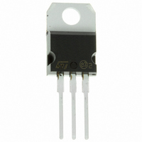
STP60NE06-16 STMicroelectronics, STP60NE06-16 Datasheet

STP60NE06-16
Specifications of STP60NE06-16
Available stocks
Related parts for STP60NE06-16
STP60NE06-16 Summary of contents
Page 1
... DC-DC & DC-AC CONVERTERS ■ SYNCHRONOUS RECTIFICATION ■ Table 2. Order Codes Part Number STP60NE06-16 STP60NE06-16FP P60NE06FP April 2004 Figure 1. Package R I DS(on Figure 2. Internal Schematic Diagram Marking Package TO-220 P60NE06 TO-220FP STP60NE06-16 STP60NE06-16FP TO-220 TO-220 FP Packaging TUBE TUBE REV 1/11 ...
Page 2
... STP60NE06- kΩ ° 100 ° °C C ≤ V( ≤ BR)DSS j JMAX Parameter Max Max Parameter max, δ < 1 Value STP60NE06-16FP 60 60 ± 240 240 150 40 1 0.3 – 2000 6 -65 to 175 175 Value TO-220 TO220-FP 1 3.75 62.5 300 Max Value 60 350 Unit ...
Page 3
... D(on) DS(on)max MHz Test Conditions 4.7 Ω Test Conditions 4.7 Ω STP60NE06-16/FP Min. Typ. Max. Unit 60 V µA 1 µA 10 ± 100 nA Min. Typ. Max. Unit Ω 0.013 0.016 Min. Typ. Max. Unit 4600 6200 pF 580 800 pF 140 200 pF Min. Typ. ...
Page 4
... STP60NE06-16/FP Table 11. Source Drain Diode Symbol Parameter I Source-drain Current SD (1) Source-drain Current I SDM (pulsed) (2) Forward On Voltage Reverse Recovery Time rr Q Reverse RecoveryCharge rr I Reverse RecoveryCharge RRAM Note: 1. Pulse width limited by safe operating area 2. Pulsed: Pulse duration = 300 µs, duty cycle 1.5 % Figure 3 ...
Page 5
... Figure 7. Output Characteristics Figure 9. Transconductance Figure 11. Gate Charge vs Gate-source Voltage STP60NE06-16/FP Figure 8. Transfer Characteristics Figure 10. Static Drain-source On Resistance Figure 12. Capacitance Variations 5/11 ...
Page 6
... STP60NE06-16/FP Figure 13. Normalized Gate Thresold Voltage vs Temperature Figure 15. Source-drain Diode Forward Characteristics 6/11 Figure 14. Normalized On Resistance vs Temperature ...
Page 7
... Figure 16. Unclamped Inductive Load Test Circuit Figure 18. Switching Times Test Circuits For Resistive Load Figure 20. Test Circuit For Inductive Load Switching And Diode Recovery Times STP60NE06-16/FP Figure 17. Unclamped Inductive Waveforms Figure 19. Gate Charge Test Circuit 7/11 ...
Page 8
... STP60NE06-16/FP PACKAGE MECHANICAL Table 12. TO-220 Mechanical Data Symbol Min A 4.40 b 0.61 b1 1.15 c 0.49 D 15. 2.40 e1 4.95 F 1.23 H1 6. 3.50 L20 L30 ØP 3.75 Q 2.65 Figure 21. TO-220 Package Dimensions Note: Drawing is not to scale. 8/11 millimeters Typ Max 4.60 0.88 1.70 0.70 15 ...
Page 9
... H V Ø STP60NE06-16/FP inches Min Typ 0.173 0.181 0.098 0.106 0.039 0.051 0.098 0.108 0.016 0.027 0.030 0.039 0.045 0.066 0.045 0.066 0.195 0.204 0.094 0.106 0.393 0.409 0.630 1 ...
Page 10
... STP60NE06-16/FP REVISION HISTORY Table 14. Revision History Date Revision December-1997 1 14-Apr-2004 2 10/11 Description of Changes First Issue Stylesheet update. No content change. ...
Page 11
... All other names are the property of their respective owners Australia - Belgium - Brazil - Canada - China - Czech Republic - Finland - France - Germany - Hong Kong - India - Israel - Italy - Japan - Malaysia - Malta - Morocco - Singapore - Spain - Sweden - Switzerland - United Kingdom - United States © 2004 STMicroelectronics - All rights reserved STMicroelectronics GROUP OF COMPANIES www.st.com STP60NE06-16/FP 11/11 ...


