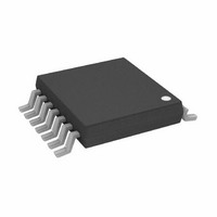
AD8612ARUZ Analog Devices Inc, AD8612ARUZ Datasheet

AD8612ARUZ
Specifications of AD8612ARUZ
Available stocks
Related parts for AD8612ARUZ
AD8612ARUZ Summary of contents
Page 1
FEATURES 4 ns propagation delay Single-supply operation 100 MHz input Latch function APPLICATIONS High speed timing Clock recovery and clock distribution Line receivers Digital communications Phase detectors High speed sampling Read channel ...
Page 2
AD8611/AD8612 TABLE OF CONTENTS Features .............................................................................................. 1 Applications....................................................................................... 1 Pin Configurations ........................................................................... 1 General Description ......................................................................... 1 Revision History ............................................................................... 2 Specifications..................................................................................... 3 Absolute Maximum Ratings............................................................ 5 Thermal Resistance ...................................................................... 5 ESD Caution.................................................................................. 5 Pin Configurations and Function Descriptions ........................... ...
Page 3
SPECIFICATIONS V+ = 5.0 V, V− 25°C, unless otherwise noted. GND A Table 1. Parameter INPUT CHARACTERISTICS Offset Voltage Offset Voltage Drift Input Bias Current Input Offset Current Input Common-Mode Voltage Range Common-Mode ...
Page 4
AD8611/AD8612 V+ = 3.0 V, V− = VGND = 25°C, unless otherwise noted. A Table 2. Parameter INPUT CHARACTERISTICS Offset Voltage Input Bias Current Input Common-Mode Voltage Range Common-Mode Rejection Ratio OUTPUT CHARACTERISTICS Output High Voltage ...
Page 5
ABSOLUTE MAXIMUM RATINGS Table 3. Parameter Total Analog Supply Voltage Digital Supply Voltage 1 Input Voltage Differential Input Voltage Output Short-Circuit Duration to GND Storage Temperature Range R, RU, RM Packages Operating Temperature Range Junction Temperature Range R, RU, RM ...
Page 6
AD8611/AD8612 PIN CONFIGURATIONS AND FUNCTION DESCRIPTIONS AD8611 IN IN– GND 3 TOP VIEW 6 (Not to Scale) V– LATCH 4 5 Figure 4. 8-Lead Narrow Body SOIC Pin Configuration Table 5. Pin Function ...
Page 7
TYPICAL PERFORMANCE CHARACTERISTICS OVERDRIVE > 10mV PD– –50 – TEMPERATURE (°C) Figure 7. Propagation Delay vs. Temperature 18 16 PD– PD+ 8 ...
Page 8
AD8611/AD8612 1 1.0 0 0.6 0.4 0.2 0 –60 –40 – TEMPERATURE (°C) Figure 13. Offset Voltage vs. Temperature 25° ...
Page 9
–2.5 –3 –3.5 –4.0 –4 TEMPERATURE (°C) Figure 19. I vs. Temperature GND 0 –0.5 –1 –1.5 –2 ...
Page 10
AD8611/AD8612 APPLICATIONS OPTIMIZING HIGH SPEED PERFORMANCE As with any high speed comparator or amplifier, proper design and layout of the AD8611/AD8612 should be used to ensure optimal performance. Excess stray capacitance or improper grounding can limit the maximum performance of ...
Page 11
OUTPUT LOADING CONSIDERATIONS The AD8611 can deliver output current without increasing its propagation delay. The outputs of the device should not be connected to more than 40 TTL input logic gates or drive less than ...
Page 12
AD8611/AD8612 voltage is greater than V , and does not switch high again until HI the input voltage is less than given in Equation − ...
Page 13
SPICE Model * AD8611 SPICE Macro-Model Typical Values * 1/2000, Ver. 1.0 * TAM/ADSC * * Node assignments * non-inverting input * | inverting input * | | * | | * | | * | | * | | ...
Page 14
AD8611/AD8612 * CMRR = 66dB, ZERO AT 1 kHz * ECM1 30 98 RCM1 30 31 RCM2 31 98 CCM1 Latch Section * ...
Page 15
RB1 43 41 RB2 40 42 CB1 99 41 CB2 42 51 RO1 RO2 47 45 EO1 97 43 EO2 NOT Output * Q5 ...
Page 16
AD8611/AD8612 OUTLINE DIMENSIONS 3.20 3.00 2.80 5. 3.20 4.90 3.00 4.65 2. PIN 1 0.65 BSC 0.95 0.85 1.10 MAX 0.75 0.15 0.38 0.23 0.00 0.22 0.08 SEATING COPLANARITY 0.10 PLANE COMPLIANT TO JEDEC STANDARDS MO-187-AA ...
Page 17
... AD8612ARU-REEL –40°C to +85°C 1 AD8612ARUZ –40°C to +85°C 1 AD8612ARUZ-REEL –40°C to +85° Pb-free part. Package Description 8-Lead Mini Small Outline Package [MSOP] 8-Lead Mini Small Outline Package [MSOP] 8-Lead Mini Small Outline Package [MSOP] ...
Page 18
AD8611/AD8612 NOTES Rev Page ...
Page 19
NOTES Rev Page AD8611/AD8612 ...
Page 20
AD8611/AD8612 NOTES ©2006 Analog Devices, Inc. All rights reserved. Trademarks and registered trademarks are the property of their respective owners. C06010-0-8/06(A) Rev Page ...


