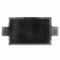
BAR 50-02V E6768 Infineon Technologies, BAR 50-02V E6768 Datasheet

BAR 50-02V E6768
Specifications of BAR 50-02V E6768
Related parts for BAR 50-02V E6768
BAR 50-02V E6768 Summary of contents
Page 1
Silicon PIN Diodes • Current-controlled RF resistor for switching and attenuating applications • Frequency range above 10 MHz GHz • Especially useful as antenna switch in mobile communication • Very low capacitance at zero volt reverse bias ...
Page 2
Maximum Ratings 25°C, unless otherwise specified A Parameter Diode reverse voltage Forward current Total power dissipation ≤ 130°C BAR50-02L ≤ 120°C BAR50-02V ≤ 115°C BAR50-03W Junction temperature Operating temperature range Storage ...
Page 3
Electrical Characteristics at T Parameter AC Characteristics Diode capacitance MHz MHz 100 MHz ...
Page 4
Diode capacitance Parameter 0.5 pF 0.4 0.35 0.3 1 MHz 100 MHz 0.25 1 GHz 1.8 GHz 0.2 0.15 0 ƒ (I Forward resistance r f ...
Page 5
Forward current BAR50-02L 120 mA 100 ƒ (T Forward current BAR50-03W 120 mA 100 ...
Page 6
Permissible Pulse Load = ƒ Fmax FDC p BAR50-02L 0.005 0.01 0.02 0.05 0.1 0 Permissible Pulse Load ...
Page 7
Permissible Pulse Load = ƒ Fmax FDC p BAR50-03W 0.005 0.1 0.2 0 ƒ (f) Isolation I ...
Page 8
Package Outline Foot Print Marking Layout (Example) Standard Packing Reel ø180 mm = 3.000 Pieces/Reel Reel ø180 mm = 8.000 Pieces/Reel (2 mm Pitch) Reel ø330 mm = 10.000 Pieces/Reel Standard 4 0.4 Cathode marking 0.93 Package SC79 0.2 M ...
Page 9
Date Code marking for discrete packages with one digit (SCD80, SC79, SC75 Month ...
Page 10
Package Outline Foot Print Marking Layout (Example) Standard Packing Reel ø180 mm = 3.000 Pieces/Reel Reel ø330 mm = 10.000 Pieces/Reel Cathode marking Package SOD323 +0.2 0.9 -0.1 +0.2 1.25 0 -0.1 ±0.05 2 Cathode marking 1 +0.1 0.3 -0.05 ...
Page 11
Package Outline Top view 2 1 Cathode marking 1) Dimension applies to plated terminal Foot Print For board assembly information please refer to Infineon website "Packages" Copper Marking Layout (Example) Standard Packing Reel ø180 mm = 15.000 Pieces/Reel Reel ø330 ...
Page 12
... For information on the types in question please contact your nearest Infineon Technologies Office. Infineon Technologies Components may only be used in life-support devices or systems with the express written approval of Infineon Technologies failure of such components can reasonably be expected to cause the failure of that life-support device or system affect the safety or effectiveness of that device or system ...


