BLF871,112 NXP Semiconductors, BLF871,112 Datasheet
BLF871,112
Specifications of BLF871,112
934062051112
Available stocks


Related parts for BLF871,112


BLF871,112 Summary of contents
Page 1
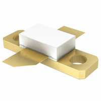
BLF871; BLF871S UHF power LDMOS transistor Rev. 04 — 19 November 2009 1. Product profile 1.1 General description A 100 W LDMOS RF power transistor for broadcast transmitter applications and industrial applications. The transistor can deliver 100 W broadband from ...
Page 2
... NXP Semiconductors Integrated ESD protection Excellent ruggedness High power gain High efficiency Excellent reliability Easy power control Compliant to Directive 2002/95/EC, regarding Restriction of Hazardous Substances (RoHS) 1.3 Applications Communication transmitter applications in the UHF band Industrial applications in the UHF band 2. Pinning information Table 2. ...
Page 3
... NXP Semiconductors 4. Limiting values Table 4. In accordance with the Absolute Maximum Rating System (IEC 60134). Symbol stg Thermal characteristics Table 5. Symbol R th(j-c) [ measured under RF conditions. th(j-c) 6. Characteristics Table 6. ° unless otherwise specified. j Symbol Parameter V drain-source breakdown voltage V (BR)DSS V gate-source threshold voltage ...
Page 4
... NXP Semiconductors V GS Fig 1. Output capacitance as a function of drain-source voltage; typical values 7. Application information Table 7. ° unless otherwise specified. h Mode of operation 2-tone, class AB DVB-T (8k OFDM) [1] Measured [dBc] with delta marker at 4.3 MHz from center frequency. [2] PAR (of output signal) at 0.01 % probability on CCDF; PAR of input signal = 9 0.01 % probability on CCDF ...
Page 5
... NXP Semiconductors 7.1 Narrowband RF figures 7.1 Fig 2. CW power gain and drain efficiency as a function of load power; typical values 7.1.2 2-Tone (dB η 0.5 A; measured in a common source DS Dq narrowband 860 MHz test circuit. Fig 3. 2-Tone power gain and drain efficiency as functions of average load power; typical ...
Page 6
... NXP Semiconductors 7.1.3 DVB (dB η 0.5 A; measured in a common source DS Dq narrowband 860 MHz test circuit. Fig 5. DVB-T power gain and drain efficiency as functions of average load power; typical values BLF871_BLF871S_4 Product data sheet 001aaj280 −15 60 IMD3 η (dBc) D (%) −25 40 −35 20 −45 − ...
Page 7
... NXP Semiconductors 7.2 Broadband RF figures 7.2.1 2-Tone 22 G (2) p (dB) ( (2) (1) η 400 500 600 700 I = 0.5 A; measured in a common source broadband Dq test circuit as described in Section ( L(AV) ( L(AV) Fig 7. 2-Tone power gain and drain efficiency as a function of frequency; typical values BLF871_BLF871S_4 Product data sheet ...
Page 8
... NXP Semiconductors 7.2.2 DVB (2) p (dB) ( (1) (2) η 400 500 600 700 I = 0.5 A; measured in a common source broadband Dq test circuit as described in Section ( L(AV) ( L(AV) Fig 9. DVB-T power gain and drain efficiency as functions of frequency; typical values PAR (dB 0.5 A; measured in a common source broadband test circuit as described in Dq PAR of input signal = 9 ...
Page 9
... NXP Semiconductors 7.3 Ruggedness in class-AB operation The BLF871 and BLF871S are capable of withstanding a load mismatch corresponding to VSWR = through all phases under the following conditions 860 MHz at rated power. 7.4 Impedance information Fig 12. Definition of transistor impedance Table 8. Simulated Z f (MHz) 300 325 ...
Page 10
... NXP Semiconductors Table 8. Simulated Z f (MHz) 925 950 975 1000 7.5 Reliability 5 10 Years TTF (0.1 % failure fraction). The reliability at pulsed conditions can be calculated as follows: TTF (0.1 %) × δ (10 (11 Fig 13. Electromigration (I BLF871_BLF871S_4 Product data sheet Typical impedance …continued and Z device impedance; impedance info at V ...
Page 11
... NXP Semiconductors 8. Test information Table 9. List of components For test circuit, see Figure 14, Figure 15 Component Description C1, C2 multilayer ceramic chip capacitor C3, C4 multilayer ceramic chip capacitor C5 multilayer ceramic chip capacitor C6 multilayer ceramic chip capacitor C7 multilayer ceramic chip capacitor C8, C9, C10, C25, multilayer ceramic chip capacitor ...
Page 12
L23 C25 L22 C24 See Table 9 for a list of components. Fig 14. Class-AB common-source broadband amplifier C11 C12 C27 C26 C20 C1 ...
Page 13
... NXP Semiconductors 40 mm Fig 15. Printed-Circuit Board (PCB) for class-AB common source amplifier BLF871_BLF871S_4 Product data sheet BLF871; BLF871S 40 mm Rev. 04 — 19 November 2009 UHF power LDMOS transistor 76.2 mm 001aaj289 © NXP B.V. 2010. All rights reserved ...
Page 14
... NXP Semiconductors R2 C26 L23 C25 L21 C24 C23 L23 See Table 9 for a list of components. Fig 16. Component layout for class-AB common source amplifier BLF871_BLF871S_4 Product data sheet C11 C9 C27 C20 C22 L20 L1 C21 C2 L7 C10 Rev. 04 — 19 November 2009 BLF871; BLF871S UHF power LDMOS transistor ...
Page 15
... NXP Semiconductors 9. Package outline Flanged LDMOST ceramic package; 2 mounting holes; 2 leads DIMENSIONS (millimetre dimensions are derived from the original inch dimensions) UNIT 4.67 5.59 0.15 9.25 9.27 mm 3.94 5.33 0.10 9.04 9.02 0.184 0.220 0.006 0.364 0.365 inch 0.155 0.210 0.004 ...
Page 16
... NXP Semiconductors Earless LDMOST ceramic package; 2 leads Dimensions (1) Unit max 4.67 5.59 0.15 9.25 9.27 mm nom min 3.94 5.33 0.10 9.04 9.02 max 0.184 0.22 0.006 0.364 0.365 inches nom min 0.155 0.21 0.004 0.356 0.355 Note 1. millimeter dimensions are derived from the original inch dimensions. ...
Page 17
... NXP Semiconductors 10. Abbreviations Table 10. Acronym CW CCDF DVB DVB-T ESD HF IMD3 LDMOS LDMOST OFDM PAR PEP RF TTF UHF VSWR 11. Revision history Table 11. Revision history Document ID Release date BLF871_BLF871S_4 20091119 • Modifications: This document now describes both the BLF871 and the BLF871S. BLF871_3 ...
Page 18
... Right to make changes — NXP Semiconductors reserves the right to make changes to information published in this document, including without limitation specifications and product descriptions, at any time and without notice ...
Page 19
... NXP Semiconductors 14. Contents 1 Product profile . . . . . . . . . . . . . . . . . . . . . . . . . . 1 1.1 General description . . . . . . . . . . . . . . . . . . . . . 1 1.2 Features . . . . . . . . . . . . . . . . . . . . . . . . . . . . . . 1 1.3 Applications . . . . . . . . . . . . . . . . . . . . . . . . . . . 2 2 Pinning information . . . . . . . . . . . . . . . . . . . . . . 2 3 Ordering information . . . . . . . . . . . . . . . . . . . . . 2 4 Limiting values Thermal characteristics . . . . . . . . . . . . . . . . . . 3 6 Characteristics . . . . . . . . . . . . . . . . . . . . . . . . . . 3 7 Application information 7.1 Narrowband RF figures . . . . . . . . . . . . . . . . . . 5 7.1 7.1.2 2-Tone 7.1.3 DVB 7.2 Broadband RF figures . . . . . . . . . . . . . . . . . . . 7 7.2.1 2-Tone ...