PD84001 STMicroelectronics, PD84001 Datasheet
PD84001
Specifications of PD84001
PD84001
Available stocks


Related parts for PD84001


PD84001 Summary of contents
Page 1
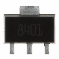
... Supplied in tape and reel ■ In compliance with the 2002/95/EC european directive Description The PD84001 is a common source N-channel, enhancement-mode lateral field-effect RF power transistor designed for high gain, broad band commercial and industrial applications. It operates common source mode at frequencies GHz. PD84001’s superior gain and efficiency makes it an ideal solution for portable radio and UHF RFID reader ...
Page 2
... Thermal data . . . . . . . . . . . . . . . . . . . . . . . . . . . . . . . . . . . . . . . . . . . . . . . 3 2 Electrical characteristics . . . . . . . . . . . . . . . . . . . . . . . . . . . . . . . . . . . . . 4 2.1 Static . . . . . . . . . . . . . . . . . . . . . . . . . . . . . . . . . . . . . . . . . . . . . . . . . . . . . 4 2.2 Dynamic . . . . . . . . . . . . . . . . . . . . . . . . . . . . . . . . . . . . . . . . . . . . . . . . . . . 4 2.3 ESD protection characteristics . . . . . . . . . . . . . . . . . . . . . . . . . . . . . . . . . . 4 2.4 Moisture sensitivity level . . . . . . . . . . . . . . . . . . . . . . . . . . . . . . . . . . . . . . . 4 3 Impedance . . . . . . . . . . . . . . . . . . . . . . . . . . . . . . . . . . . . . . . . . . . . . . . . . 5 4 Typical performance . . . . . . . . . . . . . . . . . . . . . . . . . . . . . . . . . . . . . . . . . 6 5 Test circuit . . . . . . . . . . . . . . . . . . . . . . . . . . . . . . . . . . . . . . . . . . . . . . . . 11 6 Package mechanical data . . . . . . . . . . . . . . . . . . . . . . . . . . . . . . . . . . . . 12 6.1 Thermal pad and via design . . . . . . . . . . . . . . . . . . . . . . . . . . . . . . . . . . . 14 6.2 Soldering profile . . . . . . . . . . . . . . . . . . . . . . . . . . . . . . . . . . . . . . . . . . . . 15 7 Revision history . . . . . . . . . . . . . . . . . . . . . . . . . . . . . . . . . . . . . . . . . . . 17 2/18 PD84001 ...
Page 3
... PD84001 1 Electrical data 1.1 Maximum ratings Table 2. Absolute maximum ratings (T Symbol V (BR)DSS DISS STG 1.2 Thermal data Table 3. Thermal data Symbol R thJC CASE Parameter Drain-source voltage Gate-source voltage Drain current Power dissipation Max. operating junction temperature Storage temperature Parameter Junction - case thermal resistance Electrical data = +25 ° ...
Page 4
... Test conditions = 50 mA dBm 870 MHz mA dBm 870 MHz DQ OUT = dBm 870 MHz mA 870 MHz DQ OUT Test conditions Human body model Machine model Test methodology J-STD-020B PD84001 Min. Typ. Max. Unit μA 1 μA 1 2.0 3.0 5.0 V 0.6 V 14.7 pF 13.3 pF 1.3 pF Min. ...
Page 5
... PD84001 3 Impedance Figure 2. Current conventions Table 8. Impedance data Freq. (MHz) 920 900 880 860 840 820 800 Z (Ω) GS 4.0 + j4.3 3.6 + j4.3 3.3 + j4.1 3.1 + j3.7 2.9 + j3.4 2.8 + j3.0 2.7 + j2.5 Impedance Z (Ω) DL 3.7 + j6.2 3.9 + j5.5 4.1 + j4.7 4.3 + j4.0 4 ...
Page 6
... Typical performance 4 Typical performance Figure 6/18 Figure 4. DC output characteristics PD84001 ...
Page 7
... PD84001 Figure RSS DS 3.2 3.0 2.8 2.6 2.4 2.2 2.0 1.8 1.6 1.4 1.2 1.0 0.8 0.6 0.4 0.2 0 Vds (V) CRSS Figure OSS DS Coss vs Vds Vds (V) COSS Figure Typical performance ISS Vds (V) CISS 7/18 ...
Page 8
... MHz Output power vs input power and frequency Vdd = 7.5V Idq = 50m Pin (dBm) 840 MHz 870 MHz 900 MHz Pin = 17dBm Vdd = 7.5V Idq = 50m A 820 830 840 850 860 870 880 890 900 Freq (MHz) Gain Nd PD84001 910 920 ...
Page 9
... PD84001 Figure 12. Input return loss vs frequency -10 810 820 830 840 850 860 870 880 890 900 910 920 Freq (MHz) Figure 14. Efficiency vs output power and Pout (dBm) 9V 7.5V Figure 13. Output power vs input power and 34 32 Pin = 17dBm Vdd = 7.5V 30 Idq = 50m A ...
Page 10
... Typical performance Figure 16. Gain and efficiency vs pin Gain-70mA Eff-70mA 10/18 y Freq = 520 MHz Vdd = 7. Pin (dBm) Gain-200mA Gain-50mA Eff-200mA Eff-50mA PD84001 Gain-100mA Eff-100mA ...
Page 11
... PD84001 5 Test circuit Figure 17. Test circuit schematic / 840-900 MHz Test circuit 11/18 ...
Page 12
... These packages have a lead-free second level interconnect . The category of second level interconnect is marked on the package and on the inner box label, in compliance with JEDEC Standard JESD97. The maximum ratings related to soldering conditions are also marked on the inner box label. ECOPACK trademark. ECOPACK specifications are available at: 12/18 www.st.com PD84001 ...
Page 13
... PD84001 Table 9. SOT-89 mechanical data Dim Figure 18. Package dimensions mm. Min Typ Max 1.4 1.6 0.44 0.56 0.36 0.48 0.35 0.44 0.35 0.44 4.4 4.6 1.62 1.83 2.29 2.6 1.42 1.57 2.92 3.07 3.94 4.25 0.89 1.2 Package mechanical data Inch Min ...
Page 14
... The via pattern is based on thru-hole vias with 0.203 mm to 0.330 mm finished hole size 1.2 mm grid pattern with 0.025 plating on via walls. If micro vias are used in a design suggested that the quantity of vias be increased by a 4:1 ratio to achieve similar results. Figure 19. Pad layout details 14/18 SOT-89 PD84001 ...
Page 15
... PD84001 6.2 Soldering profile Figure 20 shows the recommeded solder for devices that have Pb-free terminal plating and where a Pb-free solder is used. Figure 20. Recommended solder profile Figure 21 shows the recommeded solder for devices with Pb-free terminal plating used with leaded solder, or for devices with leaded terminal plating used with a leaded solder. ...
Page 16
... Package mechanical data Figure 22. Reel information 16/18 PD84001 ...
Page 17
... PD84001 7 Revision history Table 10. Document revision history Date 06-Dec-2006 16-May-2007 05-Jun-2007 25-Aug-2008 Revision 1 Initial release 2 Marking updated 3 Part number update 4 Updated Table 4 on page 4 Revision history Changes 17/18 ...
Page 18
... Australia - Belgium - Brazil - Canada - China - Czech Republic - Finland - France - Germany - Hong Kong - India - Israel - Italy - Japan - Malaysia - Malta - Morocco - Singapore - Spain - Sweden - Switzerland - United Kingdom - United States of America 18/18 Please Read Carefully: © 2008 STMicroelectronics - All rights reserved STMicroelectronics group of companies www.st.com PD84001 ...