SD2931-10 STMicroelectronics, SD2931-10 Datasheet
SD2931-10
Specifications of SD2931-10
SD2931-10
Available stocks


Related parts for SD2931-10


SD2931-10 Summary of contents
Page 1
... W min. with 14 dB gain @ 175 MHz OUT ■ Thermally enhanced packaging for lower junction temperatures Description The SD2931- gold metallized N-channel MOS field-effect RF power transistor. Being electrically identical to the standard SD2931 MOSFET intended for use large signal applications up to 230 MHz. The SD2931-10 is mechanical compatible to the ...
Page 2
... Dynamic . . . . . . . . . . . . . . . . . . . . . . . . . . . . . . . . . . . . . . . . . . . . . . . . . . . 4 3 Impedance data . . . . . . . . . . . . . . . . . . . . . . . . . . . . . . . . . . . . . . . . . . . . . 6 4 Typical performance . . . . . . . . . . . . . . . . . . . . . . . . . . . . . . . . . . . . . . . . . 7 5 Typical performance @ 175 MHz . . . . . . . . . . . . . . . . . . . . . . . . . . . . . . . 8 6 Test circuit . . . . . . . . . . . . . . . . . . . . . . . . . . . . . . . . . . . . . . . . . . . . . . . . . 9 7 Typical performance @ 30 MHz . . . . . . . . . . . . . . . . . . . . . . . . . . . . . . . 11 8 Test circuit @ 30 MHz . . . . . . . . . . . . . . . . . . . . . . . . . . . . . . . . . . . . . . . 12 9 Package mechanical data . . . . . . . . . . . . . . . . . . . . . . . . . . . . . . . . . . . . 13 10 Marking, packing and shipping specifications . . . . . . . . . . . . . . . . . . . 15 11 Revision history . . . . . . . . . . . . . . . . . . . . . . . . . . . . . . . . . . . . . . . . . . . 16 2/17 Doc ID 7076 Rev 7 SD2931-10 ...
Page 3
... SD2931-10 1 Electrical data 1.1 Maximum ratings ( °C). CASE Table 2. Absolute maximum ratings Symbol (1) V Drain source voltage (BR)DSS V Drain-gate voltage (R DGR V Gate-source voltage GS I Drain current D P Power dissipation DISS T Max. operating junction temperature J T Storage temperature STG 150°C J 1.2 Thermal data Table 3 ...
Page 4
... MHz DS Test conditions I = 250 175 MHz DQ = 250 mA P 150 175 MHz DQ OUT = = 250 150 175 MHz DQ OUT = 250 mA P 150 175 MHz DQ OUT = Doc ID 7076 Rev 7 SD2931-10 Min Typ Max Unit 125 V µA 50 250 nA See table below V 3 mho 480 pF 190 ...
Page 5
... SD2931-10 Table Symbol sorts Value 2.0 - 2.1 2.1 - 2.2 2.2 - 2.3 2.3 - 2.4 2.4 - 2.5 2.5 - 2.6 2.6 - 2.7 2.7 - 2.8 2.8 - 2.9 Doc ID 7076 Rev 7 Electrical characteristics Symbol Value K 2.9 - 3.0 L 3.0 - 3.1 M 3.1 - 3.2 N 3.2 - 3.3 P 3.3 - 3.4 Q 3 ...
Page 6
... Impedance data 3 Impedance data Figure 2. Impedance data Table 7. Impedance data Freq 30 MHz 175 MHz 6/17 Typical Input Impedance G Zin Z (Ω 5.7 1 2.0 Doc ID 7076 Rev Typical Drain Load Impedance S Z (Ω 0.9 2 2.4 SD2931-10 ...
Page 7
... SD2931-10 4 Typical performance Figure 3. Capacitance vs drain-source voltage 10000 1000 Ciss Coss 100 VDS, DRAIN-SOURCE VOLTAGE (V) Figure 5. Gate-source voltage vs case temperature 1.12 1.08 1.04 Id =11A 1 0.96 0.92 0.88 Vds 0.84 0.8 - Tc, CASE TEMPERATURE (°C) Figure 7. Safe operating area 100 10 ( Vds(V) (1) Current in this area may be limited by R ds(on) Figure 4 ...
Page 8
... Figure 13. Drain current vs gate-source 20 Pin =10W 15 Pin =5W Pin =2. Idq= 250mA f= 175MHz Doc ID 7076 Rev 7 SD2931-10 Output power vs input power Tc =-20 °C Tc =+25 °C Tc =+80 °C Vdd= 50V Idq= 250mA f= 175MHz Pin, INPUT POWER(W) Vdd=50V Idq=250mA f=175Mhz 50 100 150 200 ...
Page 9
... SD2931-10 6 Test circuit Figure 14. 175 MHz test circuit schematic (production test circuit) Note: All dimensions in inches Table 8. Component part list Component T1 T2 FB1 FB2, FB3 FB4 L1 PCB R1 C1, C11 C2 C3, C8 Description 4:1 transformer, 25 ohm flexible coax .090 OD 6” long 1:4 transformer, 25 ohm semi-rigid coax .141 OD 6” long Toroid X 2, 0.5” ...
Page 10
... Figure 16. 175 MHz test circuit 10/17 Description 120 pF ATC chip cap 0.01 µF ATC chip cap 30 pF ATC chip cap 91 pF ATC chip cap 1200 pF ATC chip cap 0.01 µF / 500 V chip cap 10 µ electrolytic capacitor 6.4 inches Doc ID 7076 Rev 7 SD2931-10 ...
Page 11
... SD2931-10 7 Typical performance @ 30 MHz Figure 17. Output power vs input power 250 200 150 100 0.1 0.2 Pin, INPUT POWER (W) Figure 19. Efficiency vs output power 120 Pout, OUTPUT POWER (W) Figure 21. Output power vs gate voltage 200 150 100 VGS GATE-SOURCE VOLTAGE (V) Figure 18. Power gain vs output power ...
Page 12
... Woven Fiberglass, 1 oz. Copper, 2 Sides, εr = 2.55 1 KΩ chip resistor 680 Ω wirewound resistor 0.1 µF ATC chip cap 750 pF ATC chip cap 470 pF ATC chip cap 10 µ electrolytic capacitor 100 µ electrolytic capacitor Doc ID 7076 Rev 7 SD2931-10 ...
Page 13
... SD2931-10 9 Package mechanical data In order to meet environmental requirements, ST offers these devices in different grades of ® ECOPACK packages, depending on their level of environmental compliance. ECOPACK specifications, grade definitions and product status are available at: www.st.com. ECOPACK trademark. Doc ID 7076 Rev 7 Package mechanical data ® 13/17 ...
Page 14
... Doc ID 7076 Rev 7 SD2931-10 Inch Min Typ Max 0.219 0.230 0.125 0.245 0.255 0.720 0.730 0.125 0.970 0.980 0.495 0.505 0.003 0.007 0.083 ...
Page 15
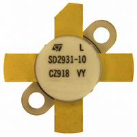
... SD2931-10 10 Marking, packing and shipping specifications Table 10. Packing and shipping specifications Order codes SD2931-10 Figure 25. Marking drawing Table 11. Marking specifications Symbol xxx VY MAR Marking, packing and shipping specifications Pcs per Dry pack Packaging tray humidity Plastic tray 25 < Description Wafer process code ...
Page 16
... Revision history Table 12. Document revision history Date 09-Sep-2004 17-Jun-2004 04-Mar-2008 08-Feb-2011 16/17 Revision 4 Table 5: Dynamic on page 4 5 Updated Table 4: Static (per Updated 6 VGS sorts on page 5 Chapter 10: Marking, packing and shipping 7 Inserted Doc ID 7076 Rev 7 SD2931-10 Changes side), Table 5: Dynamic Table 6: and specifications. ...
Page 17
... SD2931-10 Information in this document is provided solely in connection with ST products. STMicroelectronics NV and its subsidiaries (“ST”) reserve the right to make changes, corrections, modifications or improvements, to this document, and the products and services described herein at any time, without notice. All ST products are sold pursuant to ST’s terms and conditions of sale. ...