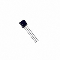
2N5064 Littelfuse / Teccor Brand Thyristors, 2N5064 Datasheet - Page 4

2N5064
Manufacturer Part Number
2N5064
Description
SCR SENSITIVE GATE 0.8A 200V
Manufacturer
Littelfuse / Teccor Brand Thyristors
Datasheet
1.S2004DS2RP.pdf
(12 pages)
Specifications of 2N5064
Scr Type
Sensitive Gate
Voltage - Off State
200V
Voltage - Gate Trigger (vgt) (max)
800mV
Voltage - On State (vtm) (max)
1.7V
Current - On State (it (av)) (max)
510mA
Current - On State (it (rms)) (max)
800mA
Current - Gate Trigger (igt) (max)
200µA
Current - Hold (ih) (max)
5mA
Current - Off State (max)
1µA
Current - Non Rep. Surge 50, 60hz (itsm)
16A, 20A
Operating Temperature
-40°C ~ 110°C
Mounting Type
Through Hole
Package / Case
TO-92-3 (Standard Body), TO-226
Current - On State (it (rms) (max)
800mA
Lead Free Status / RoHS Status
Lead free / RoHS Compliant
Available stocks
Company
Part Number
Manufacturer
Quantity
Price
Company:
Part Number:
2N5064
Manufacturer:
TECCOR
Quantity:
11 250
Company:
Part Number:
2N5064
Manufacturer:
HONEWELL
Quantity:
3
Part Number:
2N5064
Manufacturer:
MOTOROLA/摩托罗拉
Quantity:
20 000
Company:
Part Number:
2N5064G
Manufacturer:
ON Semiconductor
Quantity:
76
Sensitive SCRs
Specific Test Conditions
di/dt — Maximum rate-of-change of on-state current; I
dv/dt — Critical rate-of-rise of forward off-state voltage
I
I
I
I
I
I
I
P
P
t
t
V
V
V
V
http://www.littelfuse.com
+1 972-580-7777
2
DRM
GT
GM
H
T
TSM
gt
q
t — RMS surge (non-repetitive) on-state current for period of 8.3 ms
G(AV)
GM
DRM
GRM
GT
TM
— Maximum on-state current
— DC holding current; initial on-state current = 20 mA
— Circuit commutated turn-off time
— Gate controlled turn-on time gate pulse = 10 mA; minimum
TYPE
— DC gate trigger current V
— Peak gate current
10 A
width ≥15 µsec with ≤0.1 µs rise time
for fusing
width = 15 µS with rise time ≤0.1 µs
— DC gate trigger voltage; V
— Peak on-state voltage
6 A
8 A
— Peak one-cycle forward surge current
— Peak gate power dissipation
and I
and V
— Peak reverse gate voltage
— Average gate power dissipation
RRM
RRM
— Peak off-state current at V
— Repetitive peak off-state forward and reverse voltage
S2006LS2
S4006LS2
S6006LS2
S2006LS3
S4006LS3
S6006LS3
S2008LS2
S4008LS2
S6008LS2
S2008LS3
S4008LS3
S6008LS3
S2010LS2
S4010LS2
S6010LS2
S2010LS3
S4010LS3
S6010LS3
Isolated
K
TO-220
A
See “Package Dimensions” section for variations. (11)
G
D
D
= 6 V dc; R
S2006FS21
S4006FS21
S6006FS21
S2006FS31
S4006FS31
S6006FS31
S2008FS21
S4008FS21
S6008FS21
S2008FS31
S4008FS31
S6008FS31
S2010FS21
S4010FS21
S6010FS21
S2010FS31
S4010FS31
S6010FS31
K
= 6 V dc; R
TO-202
A
Part Number
G
A
DRM
L
= 100 Ω
L
and V
= 100 Ω
Non-isolated
S2006VS2
S4006VS2
S6006VS2
S2006VS3
S4006VS3
S6006VS3
S2008VS2
S4008VS2
S6008VS2
S2008VS3
S4008VS3
S6008VS3
S2010VS2
S4010VS2
S6010VS2
S2010VS3
S4010VS3
S6010VS3
K
TO-251
V-Pak
A
RRM
GT
A
= 50 mA pulse
G
A
S2006DS2
S4006DS2
S6006DS2
S2006DS3
S4006DS3
S6006DS3
S2008DS2
S4008DS2
S6008DS2
S2008DS3
S4008DS3
S6008DS3
S2010DS2
S4010DS2
S6010DS2
S2010DS3
S4010DS3
S6010DS3
TO-252
D-Pak
E5 - 4
K
A
G
General Notes
•
•
•
•
•
•
•
I
T(RMS)
MAX
Teccor 2N5064 and 2N6565 Series devices conform to all JEDEC
registered data. See specifications table on pages E5 - 2 and
E5 - 3.
The case lead temperature (
dimensional outline drawings in the “Package Dimensions” section
of this catalog.
All measurements (except I
R
All measurements are made at 60 Hz with a resistive load at an
ambient temperature of +25 °C unless otherwise specified.
Operating temperature (T
devices, -65 °C to +125 °C for 2N Series devices, -40 °C to
+125 °C for “TCR” Series, and -40 °C to +110 °C for all others.
Storage temperature range (T
devices, -40 °C to +150 °C for TO-202 and Compak devices, and
-40 °C to +125 °C for all others.
Lead solder temperature is a maximum of +230 °C for 10 seconds
maximum ≥1/16" (1.59 mm) from case.
10
10
10
10
10
10
6
6
6
6
6
6
8
8
8
8
8
8
GK
Amps
= 1 kΩ unless otherwise noted.
(1)
I
T
I
MAX
T(AV)
3.8
3.8
3.8
3.8
3.8
3.8
5.1
5.1
5.1
5.1
5.1
5.1
6.4
6.4
6.4
6.4
6.4
6.4
V
V
DRM
Volts
MIN
200
400
600
200
400
600
200
400
600
200
400
600
200
400
600
200
400
600
RRM
&
J
) is -65 °C to +110 °C for EC Series
GT
T
) are made with an external resistor
C
S
) is -65 °C to +150 °C for TO-92
or T
(2) (12)
µAmps
MAX
200
200
200
500
500
500
200
200
200
500
500
500
200
200
200
500
500
500
I
GT
L
) is measured as shown on
Thyristor Product Catalog
25 °C
MAX
T
C
5
5
5
5
5
5
5
5
5
5
5
5
5
5
5
5
5
5
(20) (21)
©2004 Littelfuse, Inc.
I
µAmps
=
DRM
I
RRM
110 °C
&
MAX
T
250
250
250
250
250
250
250
250
250
250
250
250
250
250
250
250
250
250
C
=
Data Sheets
(3) (10)
V
Volts
MAX
1.6
1.6
1.6
1.6
1.6
1.6
1.6
1.6
1.6
1.6
1.6
1.6
1.6
1.6
1.6
1.6
1.6
1.6
TM


