2N5064,112 NXP Semiconductors, 2N5064,112 Datasheet - Page 2
2N5064,112
Manufacturer Part Number
2N5064,112
Description
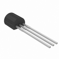
THYRISTOR 8A 200V TO-92
Manufacturer
NXP Semiconductors
Type
SCRr
Datasheet
1.2N5064112.pdf
(4 pages)
Specifications of 2N5064,112
Package / Case
TO-92-3 (Standard Body), TO-226
Scr Type
Sensitive Gate
Voltage - Off State
200V
Voltage - Gate Trigger (vgt) (max)
800mV
Voltage - On State (vtm) (max)
1.71V
Current - On State (it (av)) (max)
510mA
Current - On State (it (rms)) (max)
800mA
Current - Gate Trigger (igt) (max)
200µA
Current - Hold (ih) (max)
5mA
Current - Off State (max)
10µA
Current - Non Rep. Surge 50, 60hz (itsm)
10A @ 60Hz
Operating Temperature
-65°C ~ 125°C
Mounting Type
Through Hole
Current - On State (it (rms) (max)
800mA
Breakover Current Ibo Max
10 A
Rated Repetitive Off-state Voltage Vdrm
200 V
Off-state Leakage Current @ Vdrm Idrm
0.01 mA
Forward Voltage Drop
1.7 V
Gate Trigger Voltage (vgt)
0.8 V
Maximum Gate Peak Inverse Voltage
5 V
Gate Trigger Current (igt)
0.2 mA
Holding Current (ih Max)
5 mA
Mounting Style
SMD/SMT
Maximum Operating Temperature
+ 125 C
Minimum Operating Temperature
- 65 C
Repetitive Peak Off-state Volt
200V
Off-state Voltage
200V
Average On-state Current
510mA
Hold Current
5mA
Gate Trigger Current (max)
200uA
Gate Trigger Voltage (max)
800mV
Peak Reverse Gate Voltage
5V
Package Type
SPT
Peak Repeat Off Current
10uA
Peak Surge On-state Current (max)
10A
On State Voltage(max)
1.7@1.2AV
Mounting
Through Hole
Pin Count
3
Operating Temp Range
-65C to 125C
Operating Temperature Classification
Military
Lead Free Status / RoHS Status
Lead free / RoHS Compliant
Lead Free Status / RoHS Status
Lead free / RoHS Compliant, Lead free / RoHS Compliant
Other names
2N5064P
2N5064P
568-4443
934002930112
2N5064P
568-4443
934002930112


Philips Semiconductors
THERMAL RESISTANCES
STATIC CHARACTERISTICS
T
DYNAMIC CHARACTERISTICS
T
1 This measurement is made with the case mounted "flat side down" on a heatsink and held in position by means of
a metal clamp over the curved surface.
October 1997
Thyristor
sensitive gate
SYMBOL PARAMETER
R
R
c
SYMBOL PARAMETER
I
I
I
V
V
I
c
SYMBOL PARAMETER
dV
t
t
GT
L
H
D
gt
q
= 25 ˚C, R
= 25 ˚C, R
T
GT
th j-c
th j-a
, I
D
R
/dt
GK
GK
Thermal resistance
junction to case
Thermal resistance
junction to ambient
Gate trigger current
Latching current
Holding current
On-state voltage
Gate trigger voltage
Off-state leakage current
Critical rate of rise of
off-state voltage
Gate controlled turn-on
time
Circuit commutated
turn-off time
= 1 k unless otherwise stated
= 1 k unless otherwise stated
CONDITIONS
see note:
CONDITIONS
T
T
V
circuit
V
V
I
T
T
T
V
circuit
V
T
T
CONDITIONS
V
exponential waveform; R
I
dI
V
I
dV
T
TM
TM
c
c
j
j
j
j
j
D
D
D
D
D
DM
DM
G
= 1.2 A peak; t
= 25 ˚C
= -65 ˚C
= 125 ˚C
= 25 ˚C
= 125 ˚C
= 25 ˚C
= -65 ˚C
D
/dt = 0.1 A/ s
= V
= 12 V; R
= 12 V; R
= V
= V
= 2 A; V
= 1.6 A; V
/dt = 2 V/ s; R
= 67% V
= 67% V
DRM(max)
DRM(max)
DRM(max)
1
D
GK
GK
DRM(max)
= V
DRM(max)
; R
; R
; V
R
= 35 V; dI
= 1 k
= 1 k
R
L
L
2
DRM(max)
p
= 100 ; gate open
= 100 ; gate open
= V
= 300 s;
GK
; T
; T
= 1 k
RRM(max)
j
j
; I
= 125 ˚C;
= 125 ˚C;
TM
G
GK
= 10 mA;
/dt = 30 A/ s;
= 1 k
0.01
MIN.
MIN.
MIN.
0.1
-
-
-
-
-
-
-
-
-
-
-
-
-
-
TYP.
TYP.
TYP.
200
100
25
2
-
-
-
-
-
-
-
-
-
-
-
Product specification
MAX.
MAX.
MAX.
200
350
1.7
0.8
1.2
75
10
50
6
5
-
-
-
-
-
2N5064
Rev 1.200
UNIT
UNIT
UNIT
V/ s
K/W
K/W
mA
mA
V
V
V
V
A
A
A
A
s
s
Related parts for 2N5064,112
Image
Part Number
Description
Manufacturer
Datasheet
Request
R


Part Number:
Description:
NXP Semiconductors designed the LPC2420/2460 microcontroller around a 16-bit/32-bitARM7TDMI-S CPU core with real-time debug interfaces that include both JTAG andembedded trace
Manufacturer:
NXP Semiconductors
Datasheet:

Part Number:
Description:
NXP Semiconductors designed the LPC2458 microcontroller around a 16-bit/32-bitARM7TDMI-S CPU core with real-time debug interfaces that include both JTAG andembedded trace
Manufacturer:
NXP Semiconductors
Datasheet:
Part Number:
Description:
NXP Semiconductors designed the LPC2468 microcontroller around a 16-bit/32-bitARM7TDMI-S CPU core with real-time debug interfaces that include both JTAG andembedded trace
Manufacturer:
NXP Semiconductors
Datasheet:
Part Number:
Description:
NXP Semiconductors designed the LPC2470 microcontroller, powered by theARM7TDMI-S core, to be a highly integrated microcontroller for a wide range ofapplications that require advanced communications and high quality graphic displays
Manufacturer:
NXP Semiconductors
Datasheet:
Part Number:
Description:
NXP Semiconductors designed the LPC2478 microcontroller, powered by theARM7TDMI-S core, to be a highly integrated microcontroller for a wide range ofapplications that require advanced communications and high quality graphic displays
Manufacturer:
NXP Semiconductors
Datasheet:
Part Number:
Description:
The Philips Semiconductors XA (eXtended Architecture) family of 16-bit single-chip microcontrollers is powerful enough to easily handle the requirements of high performance embedded applications, yet inexpensive enough to compete in the market for hi
Manufacturer:
NXP Semiconductors
Datasheet:
Part Number:
Description:
The XA-S3 device is a member of Philips Semiconductors? XA(eXtended Architecture) family of high performance 16-bitsingle-chip microcontrollers
Manufacturer:
NXP Semiconductors
Datasheet:

Part Number:
Description:
The NXP BlueStreak LH75401/LH75411 family consists of two low-cost 16/32-bit System-on-Chip (SoC) devices
Manufacturer:
NXP Semiconductors
Datasheet:
Part Number:
Description:
The NXP LPC3130/3131 combine an 180 MHz ARM926EJ-S CPU core, high-speed USB2
Manufacturer:
NXP Semiconductors
Datasheet:
Part Number:
Description:
The NXP LPC3141 combine a 270 MHz ARM926EJ-S CPU core, High-speed USB 2
Manufacturer:
NXP Semiconductors
Part Number:
Description:
The NXP LPC3143 combine a 270 MHz ARM926EJ-S CPU core, High-speed USB 2
Manufacturer:
NXP Semiconductors

Part Number:
Description:
The NXP LPC3152 combines an 180 MHz ARM926EJ-S CPU core, High-speed USB 2
Manufacturer:
NXP Semiconductors
Part Number:
Description:
The NXP LPC3154 combines an 180 MHz ARM926EJ-S CPU core, High-speed USB 2
Manufacturer:
NXP Semiconductors