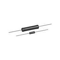
G, GN
Vishay Dale
Notes
• G002, G005, G05C, and G010: Core consists of beryllium oxide ceramic
• Models are not available lead (Pb)-free: G001...380 and G003…380
• Shaded area indicates most popular models
(1)
* Pb containing terminations are not RoHS compliant, exemptions may apply
** Please see document “Vishay Material Category Policy”:
www.vishay.com
1
THE PRODUCTS DESCRIBED HEREIN AND THIS DOCUMENT ARE SUBJECT TO SPECIFIC DISCLAIMERS, SET FORTH AT
GLOBAL MODEL
STANDARD ELECTRICAL SPECIFICATIONS
GLOBAL
MODEL
G001...80
G001...380
G002
G003...80
G003...380
G005
G05C
G010
TECHNICAL SPECIFICATIONS
PARAMETER
Temperature Coefficient
Maximum Working Voltage
Insulation Resistance
Terminal Strength
Operating Temperature Range
Power Rating
GLOBAL PART NUMBER INFORMATION
Global Part Numbering example: G00310R00FS7080
Historical Part Numbering example: G-3-80 10 1 % S70
Vishay Dale G models have two power ratings, depending on operation temperature and stability requirements
(See Standard
Specifications
Global Model
column for
Electrical
options)
HISTORICAL MODEL
G
G-3-80
0
MODEL
G-1-80
G-1-380
G-2
G-3-80
G-3-380
G-5
G-5C
G-10
HIST.
RESISTANCE VALUE
0
Wirewound Resistors, Miniature, Industrial,
10K00 = 10 k
K = Thousand
15R00 = 15
R = Decimal
U ± 0.05 %
RATING
to ± 5 %
POWER
P
25 °C
3
1.0
1.0
1.5
2.0
2.0
4.0
5.0
7.0
Precision Power, Silicone Coated
W
ppm/°C
(1)
UNIT
For technical questions, contact:
1
°C
lb
V
-
RESISTANCE VALUE
RATING
to ± 5 %
POWER
P
V ± 3 %
TOLERANCE CODE
25 °C
This document is subject to change without notice.
10.0
5.0
7.0
Characteristic U = + 250 °C max. hot spot temperature, ± 0.5 % max. R in 2000 h load life
0
Characteristic V = + 350 °C max. hot spot temperature, ± 3.0 % max. R in 2000 h load life
-
-
-
-
-
10
A = 0.05 %
C = 0.25 %
K = 10.0 %
D = 0.5 %
B = 0.1 %
F = 1.0 %
J = 5.0 %
W
(1)
R
www.vishay.com/doc?99902
0.499 to 25.7K
RESISTANCE
0.499 to 6.5K
0.499 to 8.6K
1.0 to 2.74K
5 minimum for G001...80 thru G003...380, 10 minimum for all others
1.0 to 1.3K
RANGE
± 90 for below 1 ; ± 50 for 1 to 9.9 ; ± 20 for 10 and above
± 0.05 %
1.0 to 1K
Characteristic U = - 65 to + 250, characteristic V = - 65 to + 350
1000 M minimum dry, 100 M minimum after moisture test
0
-
-
E70 = Lead (Pb)-free, tape/reel (smaller than G010)
E73 = Lead (Pb)-free, tape/reel (G010 and larger)
S70 = Tin/lead, tape/reel (smaller than G010)
ww2bresistors@vishay.com
0
FEATURES
• From 1.4 to 4 times higher power ratings than
• High temperature coating (> 350 °C)
• Complete welded construction
• Meets applicable requirements of MIL-PRF-26
• Available in non-inductive styles (type GN) with
• Excellent
• MIL-PRF-26 qualified, type RW resistors can
• Compliant to RoHS Directive 2002/95/EC
S73 = Tin/lead, tape/reel (G010 and larger)
conventional resistors of equivalent size
Aryton-Perry winding for lowest reactive
components
resistance shift < 0.5 %)
be found at:
G RESISTOR CHARACTERISTICS
0.499 to 2.74K
0.499 to 2.74K
0.499 to 25.7K
RESISTANCE
0.499 to 1.3K
0.499 to 6.5K
0.499 to 8.6K
TOLERANCE CODE
0.499 to 1K
0.499 to 1K
RANGE
± 0.1 %
F
E12 = Lead (Pb)-free, bulk
B12 = Tin/lead, bulk
1 %
PACKAGING
(P x R)
S
stability
www.vishay.com/doc?30281
0.499 to 10.4K
0.499 to 2.74K
RESISTANCE
0.499 to 3.4K
0.499 to 4.9K
0.1 to 24.5K
0.1 to 32.3K
0.1 to 95.2K
0.499 to 1K
1/2
RANGE
± 0.25 %
7
in
0
operation
± 0.5 %, ± 1 %,
RESISTANCE
www.vishay.com/doc?91000
± 3 %, ± 5 %
0.1 to 10.4K
0.1 to 2.74K
0.1 to 24.5K
0.1 to 32.3K
0.1 to 95.2K
0.1 to 3.4K
0.1 to 4.9K
RANGE
Document Number: 30205
0.1 to 1K
8
PACKAGING
(typical
Revision: 06-Apr-11
S70
0
(Dash Number)
(up to 3 digits)
From 1 to 999
as applicable
SPECIAL
WEIGHT
(typical)
0.20
0.20
0.21
0.34
0.34
0.80
1.20
3.60
g


