DSS5240V-7 Diodes Inc, DSS5240V-7 Datasheet

TRANS BIPOLAR PNP -40V SOT-563

DSS5240V-7

Manufacturer Part Number
DSS5240V-7
Description
TRANS BIPOLAR PNP -40V SOT-563
Manufacturer
Diodes Inc
Datasheet

Specifications of DSS5240V-7

Transistor Type
PNP
Current - Collector (ic) (max)
1.8A
Voltage - Collector Emitter Breakdown (max)
40V
Vce Saturation (max) @ Ib, Ic
530mV @ 200mA, 2A
Current - Collector Cutoff (max)
100nA
Dc Current Gain (hfe) (min) @ Ic, Vce
300 @ 100mA, 5V
Power - Max
600mW
Frequency - Transition
150MHz
Mounting Type
Surface Mount
Package / Case
SOT-563
Lead Free Status / RoHS Status
Lead free / RoHS Compliant
Other names
DSS5240VDITR
Maximum Ratings
Thermal Characteristics
Features
Collector-Base Voltage
Collector-Emitter Voltage
Emitter-Base Voltage
Collector Current - Continuous
Peak Repetitive Collector Current (Note 3)
Peak Pulse Collector Current
Base Current (DC)
Peak Base Current
Power Dissipation (Note 4) @ T
Thermal Resistance, Junction to Ambient (Note 4) @ T
Operating and Storage Temperature Range
Notes:
DSS5240V
Document number: DS31673 Rev. 2 - 2
Epitaxial Planar Die Construction
Complementary NPN Type Available (DSS4240V)
Low Collector-Emitter Saturation Voltage, V
Surface Mount Package Suited for Automated Assembly
Ultra-Small Surface Mount Package
Lead Free/RoHS Compliant (Note 1)
"Green Device" (Note 2)
1. No purposefully added lead.
2. Diode’s Inc.’s “Green” policy can be found on our website at http://www.diodes.com/products/lead_free/index.php.
3. Operated under pulse conditions: duty cycle ≤ 20%, pulse width tp ≤ 30ms.
4. Device mounted on FR-4 PCB with minimum recommended pad layout.
Top View
Characteristic
Characteristic
@T
A
A
= 25°C
= 25°C unless otherwise specified
CE(SAT)
Bottom View
A
= 25°C
www.diodes.com
1 of 5
Mechanical Data
LOW V
Case: SOT-563
Case Material: Molded Plastic, “Green” Molding Compound. UL
Flammability Classification Rating 94V-0
Moisture Sensitivity: Level 1 per J-STD-020D
Terminals: Finish ⎯ Matte Tin annealed over Copper leadframe.
Solderable per MIL-STD-202, Method 208
Marking Information: See Page 4
Ordering Information: See Page 4
Weight: 0.003 grams (approximate)
T
Symbol
Symbol
Device Schematic
J
3
V
V
V
R
I
, T
I
CRP
I
P
CBO
CEO
EBO
I
CM
BM
I
θ JA
C
B
D
STG
1, 2, 5, 6
CE(SAT)
4
PNP SURFACE MOUNT TRANSISTOR
-55 to +150
Value
Value
-300
-1.8
600
208
-40
-40
-1
-5
-2
-3
Pin Out Configuration
6
1
5
2
DSS5240V
4
3
© Diodes Incorporated
°C/W
Unit
Unit
mW
mA
°C
V
V
V
A
A
A
A
March 2009

Related parts for DSS5240V-7

DSS5240V-7 Summary of contents

Page 1

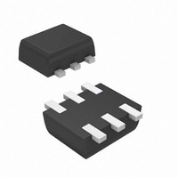
... Weight: 0.003 grams (approximate Bottom View Device Schematic Symbol V CBO V CEO V EBO CRP Symbol 25° θ STG www.diodes.com DSS5240V PNP SURFACE MOUNT TRANSISTOR Pin Out Configuration Value Unit - -300 Value Unit 600 mW °C/W 208 °C -55 to +150 March 2009 © Diodes Incorporated ...

Page 2

... C obo ⎯ f 150 T ⎯ ⎯ ⎯ ⎯ 167 t off ⎯ 140 t s ⎯ 0.1 0.01 0.001 0.1 150 100 125 www.diodes.com DSS5240V Unit Test Condition ⎯ -100μ ⎯ -10mA ⎯ -100μ -40V μA - -40V 150° -40V ...

Page 3

... Fig. 4 Typical Collector-Emitter Saturation Voltage 1.2 1.0 0 -55°C 0 25°C 0 85° 150°C 0 0.1 1,000 10,000 Fig. 6 Typical Base-Emitter Saturation Voltage f = 1MHz 10 100 www.diodes.com DSS5240V 150° 85° 25° -55° 100 1,000 -I , COLLECTOR CURRENT (mA) C vs. Collector Current ...

Page 4

... 0 0. 0.005 D = Single Pulse 0.001 0.00001 0.0001 Ordering Information (Note 6) Part Number DSS5240V-7 Notes: 6. For packaging details our website at http://www.diodes.com/datasheets/ap02007.pdf. Marking Information Date Code Key Year 2008 2009 V W Code Month Jan Feb Mar 1 2 Code ...

Page 5

... Diodes Incorporated products are not authorized for use as critical components in life support devices or systems without the expressed written approval of the President of Diodes Incorporated. DSS5240V Document number: DS31673 Rev Dimensions Value (in mm IMPORTANT NOTICE LIFE SUPPORT www.diodes.com DSS5240V 2.2 1.2 0.375 0.5 1.7 0.5 March 2009 © Diodes Incorporated ...

Related keywords