G5LE1DC12 Omron, G5LE1DC12 Datasheet

Electromechanical Relay SPDT 8ADC/10AAC 12VDC 360Ohm Through Hole

G5LE1DC12

Manufacturer Part Number
G5LE1DC12
Description
Electromechanical Relay SPDT 8ADC/10AAC 12VDC 360Ohm Through Hole
Manufacturer
Omron
Type
Power Relayr
Datasheet

Specifications of G5LE1DC12

Contact Arrangement
SPDT
Dc Coil Voltage
12 V
Coil Current
33.3 mA
Mounting
Through Hole
Relay Construction
Non-Latching
Coil Voltage Dc
12V
Contact Form
1 Form C
Voltage Rating (vdc)
125V
Voltage Rating (vac)
250V
Dropout Volt (min)
1.2VDCV
Coil Resistance
360Ohm
Pick-up Voltage (max)
9VDC
Maximum Power Rating
240W/1.2KVA
Operate Time
10ms
Contact Current Rating
8DC/10ACA
Contact Material
AgSnO2
Coil Suppression Diode
No
Push To Test Button
No
Led Indicator
No
Seal
Flux
Product Height (mm)
19mm
Product Depth (mm)
16.5mm
Product Length (mm)
22.5mm
Operating Temp Range
-25C to 85C
Pin Count
5
Mounting Style
Through Hole
Termination Style
Solder Pin
Lead Free Status / Rohs Status
Compliant
A Cubic, Single-pole 10-A Power Relay
• High Capacity (-E) and 0.8mm Contact Gap (-G) versions
• Subminiature “sugar cube” relay with universal footprint.
• Conforms to EN 61810-1. UL recognized/ CSA certified.
• UL class-F coil insulation model available
• Withstands impulse of up to 4,500 V.
• 400-mW and 360-mW coil power types available.
• RoHS Compliant
Ordering Information
Model Number Legend
1. Number of Poles
2. Contact Form
3. Enclosure Ratings
4. Contact Material
5. Insulation System
Note: When ordering, add the rated coil voltage to the model number.
Enclosure ratings
Flux protection
Fully sealed
(UL class-B coil insulation for standard model).
PCB Relay
G5LE
1:
None: SPDT
A:
None: Flux protection
4:
(Not applicable with -E and -G versions)
None: AgSnO
ASI: AgSnIn
None: Class B (Class F for -E and -G versions)
CF:
Example: G5LE-1 DC12
1 pole
SPST-NO
Fully sealed
Class F (UL and CSA only)
2
(AgSnIn for -E and -G versions)
Contact form/Style
SPDT
SPST-NO
SPDT
SPST-NO
Rated coil voltage
G5LE-1
G5LE-1-CF
G5LE-1A
G5LE-1A-CF
G5LE-14
G5LE-14-CF
G5LE-1A4
G5LE-1A4-CF
Standard
AgSnO
2
G5LE-1-ASI
G5LE-1-ASI-CF
G5LE-1A-ASI
G5LE-1A-ASI-CF
G5LE-14-ASI
G5LE-14-ASI-CF
G5LE-1A4-ASI
G5LE-1A4-ASI-CF
6. Coil Power Consumption/Coil Characteristic
7. Approved Standards
8. Approved Standards
9. Packaging
10.Rated Coil Voltage
Standard
None: Approx. 400 mW (Approx. 700mW for -G versions)
36:
G:
E:
None: UL, CSA, and VDE
None: Standard polystyrene tray
SP:
5, 9, 12, 24, 48 VDC
Approx. 360 mW (Not applicable for -G versions)
0.8mm contact gap type
High capacity type
Anti-static tube packaging
Contact material
G5LE-1-E
G5LE-1A-E
- - -
- - -
High Capacity
AgSnIn
PCB Relay
X
VDE
RC
G5LE-1-G
G5LE-1A-G
- - -
- - -
G5LE
0.8mm Contact Gap
173

Related parts for G5LE1DC12

G5LE1DC12 Summary of contents

Page 1

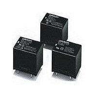
PCB Relay G5LE A Cubic, Single-pole 10-A Power Relay • High Capacity (-E) and 0.8mm Contact Gap (-G) versions • Subminiature “sugar cube” relay with universal footprint. • Conforms to EN 61810-1. UL recognized/ CSA certified. • UL class-F coil ...

Page 2

Specifications ■ Coil Ratings 700-mW Type (G5LE-G) Rated voltage Rated current Coil resistance Must operate voltage Must release voltage Max. voltage Power consumption Note: The rated current and coil resistance are measured at a coil temperature of 23°C with a ...

Page 3

Characteristics Contact resistance 100 mΩ max. Operate time 10 ms max. Release time 5 ms max. Bounce Time Operate: Approx. 0.6ms Release: Approx. 7.2ms Max. switching frequency Mechanical: Electrical: Insulation resistance 100 MΩ min. (at 500 VDC) Dielectric strength ...

Page 4

Engineering Data For standard type Max. Switching Capacity resistive 3 load DC resistive load 1 0.7 0.5 0 125 250 500 1 ,000 Switching Voltage (V) For suffix -E and -G Max. ...

Page 5

Dimensions Note: 1. All units are in millimeters unless otherwise indicated. 2. Orientation marks are indicated as follows: G5LE-1 G5LE-1A 22.5 max. (21.6)* 19.0 max. (18.5)* 0.5 3.5 0.2 1 *Average value G5LE-14 G5LE-1A4 22.5 max. (21.6)* 19.0 max. (18.5)* ...

Page 6

MEMO G5LE 178 PCB Relay ...

Page 7

... Seller within 30 days of receipt of shipment. III. PRECAUTIONS 1. Suitability THE BUYER’S SOLE RESPOINSIBILITY TO ENSURE THAT ANY OMRON PRODUCT IS FIT AND SUFFICIENT FOR USE IN A MOTORIZED VEHICLE APPLICATION. BUYER SHALL BE SOLELY RESPONSIBLE FOR DETERMINING APPROPRIATENESS OF THE PARTICULAR PRODUCT WITH RESPECT TO THE BUYER’ ...

Page 8

... THE OMRON PRODUCT IS PROPERLY RATED AND INSTALLED FOR THE INTENDED USE WITHIN THE OVERALL EQUIPMENT OR SYSTEM. Complete “Terms and Conditions of Sale” for product purchase and use are on Omron’s website at http://www.components.omron.com – under the “About Us” tab, in the Legal Matters section. ...

Related keywords