TIP102-BP Micro Commercial Components (MCC), TIP102-BP Datasheet
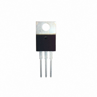
TRANSISTOR NPN 8A 100V TO-220

TIP102-BP

Manufacturer Part Number
TIP102-BP
Description
TRANSISTOR NPN 8A 100V TO-220
Manufacturer
Micro Commercial Components (MCC)
Datasheet

Specifications of TIP102-BP

Transistor Type
NPN - Darlington
Current - Collector (ic) (max)
8A
Voltage - Collector Emitter Breakdown (max)
100V
Vce Saturation (max) @ Ib, Ic
2.5V @ 80mA, 8A
Current - Collector Cutoff (max)
50µA
Dc Current Gain (hfe) (min) @ Ic, Vce
1000 @ 3A, 4V
Power - Max
80W
Mounting Type
Through Hole
Package / Case
TO-220-3 (Straight Leads)
Lead Free Status / RoHS Status
Lead free / RoHS Compliant
Frequency - Transition
-
Revision: A
Micro Commercial Components
Notes:1.High Temperature Solder Exemption Applied, see EU Directive Annex 7.
Features
Maximum Ratings
Electrical Characteristics @ 25
OFF CHARACTERISTICS
ON CHARACTERISTICS(1)
(1) Pulse Test: Pulse Width<300us, Duty Cycle<2%
V
Symbol
Symbol
M C C
V
V
CEO(SUS)
h
V
V
V
T
I
I
Lead Free Finish/RoHS Compliant(Note 1) ("P" Suffix designates
RoHS Compliant. See ordering information)
I
BE(ON)
CE(sat)
hfe
C
High DC Current Gain : h
Low Collector-Emitter Saturation Voltage
Monolithic Construction with Built-in Base-Emitter Shunt Resistors
TO-220 Compact package
Epoxy meets UL 94 V-0 flammability rating
Moisure Sensitivity Level 1
T
CEO
CBO
I
P
EBO
FE(1)
I
CEO
CBO
EBO
CP
I
STG
C
B
ob
J
D
,
Collector-Emitter Voltage
Collector-Base Voltage
Emitter-Base Voltage
Collector Current-continuous
Collector Current-peak
Base Current
Collector Dissipation @T
Derate above 25
Junction Temperature
Storage Temperature
Collector-Emitter Sustaining Voltage
Collector Cut-off Current
Emitter Cut-off Current
DC Current Gain
Collector-Emitter Saturation Voltage
Small-Signal Current Gain
Output Capacitance
Base-Emitter On Voltage
(I
(V
(V
(V
(V
(V
(V
(I
(I
(I
(I
(I
(I
(V
(V
C
C
C
C
C
C
C
=30mAdc, I
CE
CE
CB
CB
CB
BE
=3.0Adc, V
=8.0Adc, V
=3.0Adc, I
=8.0Adc, I
=8.0Adc,V
=3.0Adc,V
CB
CE
=5.0Vdc, I
=30Vdc, I
=40Vdc, I
=60Vdc, I
=80Vdc, I
=100Vdc, I
=10V, I
=50Vdc, I
E
Parameter
=0, f=0.1MHz)
B
B
CE
CE
CE
CE
=6.0mAdc)
=80mAdc)
B
B
E
E
B
Parameter
B
C
=0)
=0)
=0)
=0)
=0)
=4.0Adc)
=4.0Vdc,f=1.0MHz)
=0)
E
O
=0)
=4.0Vdc)
=4.0Vdc)
=0)
C
FE
=2500 (Typ) @ I
www.mccsemi.com
TM
C
=25
O
O
C Unless Otherwise Specified
C
TIP102
TIP100
TIP101
TIP102
TIP101
TIP102
TIP101
TIP101
  omponents
20736 Marilla Street Chatsworth

  !"#
$ %    !"#
TIP100
TIP100
TIP100
TIP101
TIP100
TIP101
TIP102
C
=4.0Adc
1000
-55 to +150
-55 to +150
Min
100
200
4.0
60
80
---
---
---
---
---
---
---
---
---
---
---
0.64
100
100
5.0
8.0
1.0
60
80
60
80
15
80
Rating
20000
Max
200
8.0
2.0
2.5
2.8
50
50
50
50
50
50
---
---
---
---
---
1 of 4
W/
O
O
Units
uAdc
uAdc
W
----
Vdc
V
V
V
A
A
A
Vdc
Vdc
mAdc
C
C
pF
O
---
C
Unit
F
A
K
G
H
J
K
N
S
DIM
D
F
L
Q
R
T
U
A
B
C
V
Silicon Transistors
H
L
G
Medium-Power
.012
.500
.045
1
.190
.045
.190
.080
.230
.380
.020
.139
.100
.045
.560
.140
-----
---
MIN
NPN Plastic
INCHES
2
N
B
TIP100
TIP101
TIP102
3
TO-220
MAX
.025
.055
.110
.580
.060
.210
.270
.420
.045
.161
.135
.115
.050
.625
.190
.250
-----
V
D
DIMENSIONS
Q
PIN 1.
PIN 2.
PIN 3.
12.70
14.22
0.30
2.29
1.14
4.83
1.14
5.84
9.65
0.51
3.53
2.54
2.04
3.56
1.15
-----
MIN
---
U
MM
T
BASE
COLLECTOR
EMITTER
J
14.73
15.88
2011/01/01
10.67
6.35
MAX
0.64
1.39
2.79
1.52
5.33
6.86
1.14
4.09
3.43
2.92
4.82
1.27
-----
C
NOTE
S
R

Related parts for TIP102-BP

TIP102-BP Summary of contents

Page 1

... TIP101 80 --- TIP101 100 --- TIP100 --- 50 TIP101 --- 50 TIP102 --- 50 TIP100 --- 50 TIP101 --- 50 TIP102 --- 50 --- 8.0 1000 20000 200 --- --- 2.0 --- 2.5 --- 2.8 4.0 --- --- 200 TIP100 TIP101 TIP102 NPN Plastic Medium-Power Silicon Transistors Unit TO-220 Units Vdc G N uAdc PIN 1. PIN 2. PIN 3. uAdc DIMENSIONS mAdc INCHES DIM ...

Page 2

... 150°C 1.0 BONDING WIRE LIMITED THERMALLY LIMITED @ 25°C 0.5 SECOND BREAKDOWN LIMITED 0.2 CURVES APPLY BELOW RATED V CEO 0.1 TIP100 0.05 TIP101 TIP102 0.02 1.0 2.0 5 COLLECTOR–EMITTER VOLTAGE (VOLTS) Figure 4. Active–Region Safe Operating Area Micro Commercial Components ...

Page 3

TIP100,101,102 10,000 5000 3000 2000 1000 500 300 200 100 1.0 2.0 5 FREQUENCY (kHz) Figure 5. Small–Signal Current Gain 20,000 10,000 150°C 5000 25°C 3000 2000 – 55°C 1000 ...

Page 4

... MCC's products are not authorized for use as critical components in life support devices or systems without the express written Counterfeiting of semiconductor parts is a growing problem in the industry. Micro Commercial Components (MCC) is taking strong measures to protect ourselves and our customers from the proliferation of counterfeit parts. MCC strongly encourages customers to purchase MCC parts either directly from MCC or from Authorized MCC Distributors who are listed by country on our web page cited below ...

Related keywords