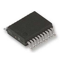
ATA5744N-TKSY 19 Atmel, ATA5744N-TKSY 19 Datasheet - Page 7

ATA5744N-TKSY 19
Manufacturer Part Number
ATA5744N-TKSY 19
Description
RF Receiver RF DATA CONTROL RECEIVER
Manufacturer
Atmel
Type
Receiverr
Datasheet
1.ATA5744N-TKQY.pdf
(20 pages)
Specifications of ATA5744N-TKSY 19
Package / Case
SSO-20
Operating Frequency
449 MHz
Operating Supply Voltage
4.5 V to 5.5 V
Maximum Operating Temperature
+ 105 C
Minimum Operating Temperature
- 40 C
Mounting Style
SMD/SMT
Noise Figure
7 dB
Lead Free Status / RoHS Status
Lead free / RoHS Compliant
4.3
4.4
4893A–RKE–11/05
Pin RSSI
ASK Demodulator and Data Filter
The output voltage of the RSSI amplifier (VRSSI) is available at pin RSSI. Using the RSSI output
signal, the signal strength of different transmitters can be distinguished. The usable input power
range P
Since different RF input networks may exhibit slightly different values for the LNA gain, the sen-
sitivity values given in the electrical characteristics refer to a specific input matching. This
matching is illustrated in
Figure 4-1.
The signal coming from the RSSI amplifier is converted into the raw data signal by the ASK
demodulator.
An automatic threshold control circuit (ATC) is employed to set the detection reference voltage
to a value where a good signal-to-noise ratio is achieved. This circuit also implies the effective
suppression of any kind of inband noise signals or competing transmitters. If the S/N ratio
exceeds 10 dB, the data signal can be detected properly.
The output signal of the demodulator is filtered by the data filter before it is fed into the digital
signal processing circuit. The data filter improves the S/N ratio as its passband can be adopted
to the characteristics of the data signal. The data filter consists of a 1st-order highpass and a
1st-order lowpass filter.
The highpass filter cut-off frequency is defined by an external capacitor connected to pin CDEM.
The cut-off frequency of the highpass filter is defined by the following formula:
Recommended values for CDEM are given in the electrical characteristics.
The cut-off frequency of the lowpass filter is defined by the selected baudrate range
(BR_Range). BR_Range is defined by the pins BR_0 and BR_1. BR_Range must be set in
accordance to the used baudrate.
fcu_DF
Ref
=
is –100 dBm to –55 dBm.
---------------------------------------------------- -
2
RSSI Characteristics
R
1
1
3.0
2.8
2.6
2.4
2.2
2.0
1.8
1.6
1.4
1.2
1.0
CDEM
Figure 3-3
-130.0
-110.0
105°C
and exhibits the best possible sensitivity.
25°C
T
-90.0
amb
= 40°C
P
Ref
min.
(dBm)
-70.0
max.
-50.0
-30.0
ATA5744
7


