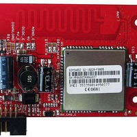
MOD-GSM-EDGE Olimex Ltd., MOD-GSM-EDGE Datasheet

MOD-GSM-EDGE
Specifications of MOD-GSM-EDGE
Related parts for MOD-GSM-EDGE
MOD-GSM-EDGE Summary of contents
Page 1
... MOD-GSM-EDGE development board All boards produced by Olimex are ROHS compliant Copyright(c) 2011, OLIMEX Ltd, All rights reserved Rev. Initial, March 2011 Page 1 Users Manual ...
Page 2
... MOD-GSM-EDGE can be connected to computer via on-board mini USB connector. Also the board can work in standalone mode, but only when the SIM card is without PIN code. In standalone mode MOD-GSM-EDGE requires usage of AT commands. It can receive information by GSM network, but if you want to operate with this information, you will need appropriate board with UEXT connected to MOD-GSM-EDGE ...
Page 3
... MODULE FEATURES Power Supply – Single Supply voltage 3.4V – 4.5V Power saving – Typical power consumption in SLEEP mode (BS-PA- MFRMS=5) is 4mA Frequency bands: GSM class – Small MS Transmit Power GMSK: 8PSK: GPRS connectivity EDGE connectivity DATA transfer TCP/IP protocol stack – Access by AT commands Temperature range SIM interface – ...
Page 4
... Speech codec modes: Main serial port Seven lines on Main serial Port CSD FAX, GPRS/EDGE services AT commands of controlling module Multiplexing function Autobauding baud rate USB interface – support an USB 2.0 Full Speed (12Mbit/s) device interface Phonebook management – support phonebook types: SM, LD, MC, RC, ME, ON, VM, LA, DC, SD, FD, BN SIM Application Toolkit – ...
Page 5
FUNCTIONAL DIAGRAM Page 5 ...
Page 6
SCHEMATIC GND2 GND4 USB GND1 GND3 VSIM,SIMDATA,SIMCLK,SIMRST 2 1 OPEN 2 1 DOW NLOAD 220uF/10V/tant C17 + CE2200uF/6.3V/LOW ESR/10x20mm RM5 + CE2200uF/6.3V/LOW ESR/10x20mm RM5 + IRLML6402 47uF/10V + 10uF/10V/1206 C14 2 2 Page 6 ...
Page 7
BOARD LAYOUT Page 7 ...
Page 8
... POWER SUPPLY CIRCUIT The MOD-GSM-EDGE board may be supplied in different ways: 1. External power supply (+9 – 12VDC), or USB power supply without using the internal backup battery. The module is powered only from external 12V and the battery is not connected. In this case: jumper BAT_E must be open ...
Page 9
... Important: 4V_E, 4V and 5V_CHG_E jumpers have to be moved together. 2. Power from +12VDC with backup battery. The module is powered with battery and allows battery charging. In this case: jumper BAT_E must be closed jumper 4V_E must be open jumper 4V must be open jumper 5V_CHG_E must be closed ...
Page 10
... CTS 7 DTR 8 CHG_CTRL PWRKEY This connector allows connecting to other Olimex boards with UEXT connector. SIM-CARD Pin # Signal Name 1 VSIM 2 SIMRST 3 SIMCLK 4 GND SIMDATA This is standard SIM card connector, to operate MOD-GSM-EDGE should have inserted valid SIM card for your operator network. Page 10 ...
Page 11
... PWR-CON Pin # Signal Name 1 +12V 2 GND This connector is used to power the MOD-GSM-EDGE. External (+9-12VDC) power source have to be applied to this pins. PWR_EXT Pin # Signal Name 5V_IN 1 2 GND 3 VBAT 4 PWR_IN 5 GPIO1 6 AUXADC BAT Pin # Signal Name 1 GND 2 TEMP_BAT 3 Via jmp BAT_E to VBAT Note: The battery doesn't support TEMP_BAT ...
Page 12
... Then SIM700D firmware could be updated through the USB PORT. If USB download mode is used, there is a popup dialog window on the computer screen when SIM700D powers up first. Users need to install the USB driver manually. So the SIM700D couldn't provide the AUTORUN function. ...
Page 13
... The MainTX/DebugTX defines whether Main TX terminal or Debug TX terminal of SIM700D module is connected to FT232RL virtual com port driver. Default state is DTX MRX/DRX The MainRX/DebugRX define whether Main RX terminal or Debug RX terminal of SIM700D module is connected to FT232RL virtual com port driver. Default state is DRX AGND_E Enable board analog ground. Default state is closed USB_PWR_E Enable USB +5 V power supply ...
Page 14
... INPUT/OUTPUT PWRKEY button – turns on the MOD-GSM-EDGE module. You can turn on the SIM700D by driving the PWRKEY to a low level voltage for period time from 500mS to 1S Status LED (red) with name STAT – indicates the state of SIM700D module. STAT is off state - SIM700D is not running ...
Page 15
MECHANICAL DIMENSIONS All measures are in inches. Page 15 ...
Page 16
... AVAILABLE DEMO SOFTWARE - EW-ARM Demo code for MOD-GSM and MOD-GSM-EDGE (high speed) GSM modules connected to STM32-LCD board by Olimex. Page 16 ...
Page 17
... ORDER CODE MOD-GSM-EDGE assembled and tested. How to order? You can order to us directly or by any of our distributors. Check our web All boards produced by Olimex are ROHS compliant Revision history: Board's revision: REV. B Manual's revision: REV. Initial www.olimex.com/dev for more info. - created July 2010 ...
Page 18
... However all warranties implied or expressed including but not limited to implied warranties of merchantability or fitness for purpose are excluded. This document is intended only to assist the reader in the use of the product. OLIMEX Ltd. shall not be liable for any loss or damage arising from the use of any information in this document or any error or omission in such information or any incorrect use of the product ...


