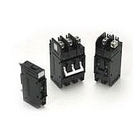
EA1-B0-12-650-21A-BB Carling Technologies, EA1-B0-12-650-21A-BB Datasheet

EA1-B0-12-650-21A-BB
Specifications of EA1-B0-12-650-21A-BB
Related parts for EA1-B0-12-650-21A-BB
EA1-B0-12-650-21A-BB Summary of contents
Page 1
... Marine Electrical & Fuel Systems (Guide PEQZ2, File E75596) Ignition Protection UL Listed UL Standard 489 Circuit Breakers, Molded Case (Guide DIVQ, File E129899) Electrical Table A: Lists UL Listed (489) & CSA Certified (C22.2 No. 5) configurations & performance capabilities as a Molded Case Circuit Breaker. ...
Page 2
Electrical Table B: Lists UL Recognized & CSA Accepted configurations & performance capabilities as a Component Supplementary Protector. Notes for Table B: 1 Requires branch circuit backup with a UL LISTED Type K5 or RK5 fuse rated 15A minimum and ...
Page 3
... Mechanical Endurance 10,000 ON-OFF operations @ 6 per minute; with rated Current and Voltage. Trip Free All E-Series Circuit Breakers will trip on overload, even when Handle is forcibly held in the ON position. Trip Indication The operating Handle moves posi- tively to the OFF position when an overload causes the breaker to trip. ...
Page 4
– Series Poles Actuator Circuit Auxiliary Switch 1 SERIES E 2 ACTUATOR Handle A Handle, one per pole 3 POLES 1 1 One 3 Three 2 Two 4 Four 4 CIRCUIT ...
Page 5
E-Series Handle UL Listed – Ordering Scheme – Series Poles Actuator Circuit 1 SERIES E 2 ACTUATOR Handle A Handle, one per pole 3 POLES 1 1 One 3 Three 2 Two ...
Page 6
Notes: 1 All dimensions are in inches [millimeters]. 2 Tolerance ±.020 [.51] unless otherwise specified. 3 0-50 amps: 10-32 & M5 Studs .625 ±.062 /15.88 ±1.574 long. 51-120 amps: 1/4-20 & M6 Studs .750 ±.062 /19.05 ±1.574 long. www.carlingtech.com E-Series ...
Page 7
... Series Trip circuit configuration shown 3” min spacing must be provided between the circuit breaker arc venting area of back connected E-Series circuit breaker and grounded obstructions. 3 All dimensions are in inches [millimeters]. 4 Tolerance ±.020 [.51] unless otherwise specified. 5 Circuit breakers must be mounted on vertical surface. 108 www.carlingtech.com ...
Page 8
... Notes: 1 All dimensions are in inches [millimeters]. 2 Tolerance ±.020 [.51] unless otherwise specified. 3 Box wire connector terminal in Series Trip circuit configuration shown. 4 Circuit breakers must be mounted on vertical surface. www.carlingtech.com E-Series Handle (Front Connected) – Form & Fit Drawings 109 ...


