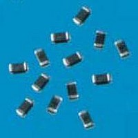
VC120631M650DP AVX Corporation, VC120631M650DP Datasheet - Page 2

VC120631M650DP
Manufacturer Part Number
VC120631M650DP
Description
Varistors 31 VDC 1J 67v
Manufacturer
AVX Corporation
Datasheet
1.VC040214X300WP.pdf
(10 pages)
Specifications of VC120631M650DP
Product
MLV
Voltage Rating Dc
31 VDC
Voltage Rating Ac
25 VAC
Clamping Voltage
65 V
Peak Surge Current
200 A
Surge Energy Rating
1 J
Capacitance
500 pF
Operating Temperature Range
- 55 C to + 125 C
Mounting
SMD/SMT
Dimensions
1.6 mm W x 3.2 mm L x 1.02 mm H
Package / Case
1206 (3216 metric)
Lead Free Status / RoHS Status
Lead free / RoHS Compliant
TransGuard
AVX Multilayer Ceramic Transient Voltage Suppressors
MARKING:
All standard surface mount TransGuard
2
Surface Mount Devices
V C 1206 05 D 150 R P
Important: For part number identification only, not for
The information below only defines the numerical value of part number
digits, and cannot be used to construct a desired set of electrical limits.
Please refer to the TransGuard
cal ratings.
0402 1.00±0.10mm (0.040"±0.004") 0.5±0.10mm (0.020"±0.004")
0603 1.60±0.15mm (0.063"±0.006") 0.8±0.15mm (0.032"±0.006")
0805 2.01±0.2mm (0.079"±0.008") 1.25±0.2mm (0.049"±0.008")
1206 3.20±0.2mm (0.126"±0.008") 1.60±0.2mm (0.063"±0.008")
1210 3.20±0.2mm (0.126"±0.008") 2.49±0.2mm (0.098"±0.008")
SIZE
CASE SIZE DESIGNATOR:
construction of part numbers.
WORKING VOLTAGE:
Where:
Where: A = 0.1J
ENERGY:
LENGTH
CASE STYLE:
PRODUCT DESIGNATOR:
03 = 3.3 VDC
05 = 5.6 VDC
09 = 9.0 VDC
12 = 12.0 VDC
14 = 14.0 VDC
®
G = 0.9J
B = 0.2J
C = 0.3J
D = 0.4J
H = 1.2J
E = 0.5J
F = 0.7J
part number data for the correct electri-
TERMINATION FINISH:
P = Ni/Sn Alloy (Plated)
PACKAGING (Pcs/Reel):
STYLE
VC0402
VC0603 1,000 4,000 10,000
VC0805 1,000 4,000 10,000
VC1206 1,000 4,000 10,000
VC1210 1,000 2,000 10,000
CLAMPING VOLTAGE:
Where: 100 = 12V
C = Chip
V = Varistor
®
®
PART NUMBER IDENTIFICATION
chips will not be marked.
150 = 18V
200 = 22V
250 = 27V
300 = 32V
390 = 42V
400 = 42V
N/A
“D”
M = 1.0J
Q = 1.3J
N = 1.1J
R = 1.7J
K = 0.6J
P = 3.0J
J = 1.5J
L = 0.8J
18 = 18.0 VDC
26 = 26.0 VDC
30 = 30.0 VDC
48 = 48.0 VDC
60 = 60.0 VDC
85 = 85.0 VDC
N/A
“R”
WIDTH
500 = 50V
560 = 60V
580 = 60V
620 = 67V
650 = 67V
101 = 100V
121 = 120V
N/A
“T”
W = 6.0J
U = 4.0-5.0J
S = 1.9-2.0J
V = 0.02J
X = 0.05J
Y = 12.0J
Z = 25.0J
T = 0.01J
10,000
N/A
N/A
N/A
N/A
“W”
Axial Leaded Devices
MARKING:
All axial TransGuards
identification, voltage/energy rating code and date code (see example below):
V A 1000 05 D 150 R L
Important: For part number identification only, not for
The information below only defines the numerical value of part number
digits, and cannot be used to construct a desired set of electrical limits.
Please refer to the TransGuard
cal ratings.
Where: AVX = Always AVX (Vendor Identification)
construction of part numbers.
TVS = Always TVS (Product Identification
05D = Working VDC and Energy Rating (Joules)
725 = Three Digit Date Code
®
are marked with vendor identification, product
Where: 8 = Last digit of year (2008)
Where: 05 = 5.6 VDC, D = 0.4J
- Transient Voltage Suppressor)
WORKING VOLTAGE:
Where: 03 = 3.3 VDC 26 = 26.0 VDC
CASE SIZE DESIGNATOR:
CASE STYLE:
PRODUCT DESIGNATOR:
®
1000 4.32mm (0.170") 2.54mm (0.100")
2000 4.83mm (0.190") 3.56mm (0.140")
SIZE
25 = Week of year
part number data for the correct electri-
AVX
TVS
05D
825
LEAD FINISH:
Copper clad steel, solder coated
PACKAGING (Pcs/Reel):
STYLE
VA1000
VA2000
CLAMPING VOLTAGE:
Where: 100 = 12V
ENERGY:
Where:
A = Axial
V = Varistor
05 = 5.6 VDC 30 = 30.0 VDC
14 = 14.0 VDC 48 = 48.0 VDC
18 = 18.0 VDC 60 = 60.0 VDC
LENGTH
150 = 18V
300 = 32V
400 = 42V
A = 0.1J
D = 0.4J
K = 2.0J
1,000
1,000
“D”
3,000
2,500
“R”
DIAMETER
580 = 60V
650 = 67V
101 = 100V
121 = 120V
7,500
5,000
“T”


