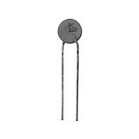
PTCCL11H211HTE Vishay, PTCCL11H211HTE Datasheet - Page 9

PTCCL11H211HTE
Manufacturer Part Number
PTCCL11H211HTE
Description
PTC CP LDD 10D5 A210 265 140 T E3
Manufacturer
Vishay
Series
662r
Type
PTCr
Specifications of PTCCL11H211HTE
Voltage - Max
265V
Current - Hold (ih) (max)
210mA
Current - Trip (it)
315mA
Current - Max
1.3A
Package / Case
Radial
Mounting Style
Through Hole
Pin Count
2
Screening Level
Commercial
Resistance @ 25c
17Ohm
Percentage Of Resistance Tolerance @ 25c
±20
Operating Temperature Min Deg. C
0C
Operating Temperature Max Deg. C
70C
Product Length (mm)
Not Requiredmm
Product Height (mm)
Not Requiredmm
Product Depth (mm)
5.5mm
Lead Free Status / RoHS Status
Contains lead / RoHS non-compliant
R Min/max
-
Time To Trip
-
Lead Free Status / RoHS Status
Contains lead / RoHS non-compliant
Other names
2322 662 52113
232266252113
BC1372
PTCCL11H211HBC
232266252113
BC1372
PTCCL11H211HBC
BCcomponents
I
low ohmic to high ohmic state at rated voltage.
When other voltages are present after tripping, the I
will allow higher overload currents to pass the PTC.
Example
What maximum overload current is allowed for a thermistor type 2322 662 52513 at 0 C and a maximum voltage after
tripping of 180 V
2000 Oct 13
max
At 0 C this gives 1.68 A
I
I
PTC thermistors for
overload protection
max
max
as stated in Tables 3, 4 and 5 is the maximum overload current that may flow through the PTC when passing from the
at 230 V and 25 C = 1.5 A
at 180 V and 25 C = 1.85 A
RMS
I
(%)
max
:
200
150
100
80
0
RMS
maximum overload current; see Fig.2.
RMS
RMS
: see Table 5.
(180 V
40
Fig.3 I
50
RMS
= 78% of 230 V
max
max
70
as a function of voltage.
value can be derived from the above Fig.3. Voltages below V
9
100
RMS
gives 123% of I
120
30 to 60 V, 145 V and
150
265 V (T
max
).
V
rated
CCB701
(%)
Product specification
s
= 140 C)
rated


