UNR32AT00L Panasonic - SSG, UNR32AT00L Datasheet
UNR32AT00L
Manufacturer Part Number
UNR32AT00L
Description
TRANS NPN W/RES 80 HFE SSS MINI
Manufacturer
Panasonic - SSG
Specifications of UNR32AT00L
Transistor Type
NPN - Pre-Biased
Current - Collector (ic) (max)
80mA
Voltage - Collector Emitter Breakdown (max)
50V
Resistor - Base (r1) (ohms)
22K
Resistor - Emitter Base (r2) (ohms)
47K
Dc Current Gain (hfe) (min) @ Ic, Vce
80 @ 5mA, 10V
Vce Saturation (max) @ Ib, Ic
250mV @ 300µA, 10mA
Current - Collector Cutoff (max)
500nA
Frequency - Transition
150MHz
Power - Max
100mW
Mounting Type
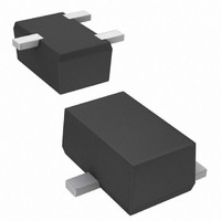
Surface Mount
Package / Case
SSS Mini3-F1
Lead Free Status / RoHS Status
Lead free / RoHS Compliant
Other names
UNR32AT00LTR


Transistors with built-in Resistor
UNR32AT
Silicon NPN epitaxial planar type
For digital circuits
Features
Features
Absolute Maximum Ratings
Absolute Maximum Ratings
Electrical Characteristics
Electrical Characteristics
Note) Measuring methods are based on JAPANESE INDUSTRIAL STANDARD JIS C 7030 measuring methods for transistors.
Publication date: March 2005
Suitable for high-density mounting and downsizing of the equipment
Suitable for high-density mounting and downsizing of the equipment
Contribute to low power consumption
Contribute to low power consumption
Collector-base voltage (Emitter open)
Collector-emitter voltage (Base open)
Collector current
Total power dissipation
Junction temperature
Storage temperature
Collector-base voltage (Emitter open)
Collector-emitter voltage (Base open)
Collector-base cutoff current (Emitter open)
Collector-emitter cutoff current (Base open)
Emitter-base cutoff current (Collector open)
Forward current transfer ratio
Collector-emitter saturation voltage
Output voltage high-level
Output voltage low-level
Input resistance
Resistance ratio
Transition frequency
Parameter
Parameter
T
a
a
a
This product complies with the RoHS Directive (EU 2002/95/EC).
= 25
= 25
T
a
a
a
= 25
= 25
°C±3°C
Symbol
V
V
T
T
T
°C
P
I
T
T
T
CBO
CEO
Symbol
stg
stg
C
V
R
T
j
j
V
V
I
I
I
V
V
1
h
h
h
CE(sat)
CBO
CEO
EBO
R
f
f
f
CBO
CEO
FE
FE
OH
OL
/ R
/ R
/ R
T
T
1
2
2
–55 to +125
Rating
I
I
V
V
V
V
I
V
V
V
C
C
C
C
C
C
C
C
C
100
125
CB
CE
CE
CE
EB
CE
CE
CE
CC
CC
CC
CC
CC
CC
CB
50
50
80
= 10
= 10
= 2 mA, I
= 2 mA, I
= 10 mA, I
= 10 mA, I
= 50 V, I
= 50 V, I
= 50 V, I
= 6 V, I
= 10 V, I
= 10 V, I
= 5 V, V
= 5 V, V
= 5 V, V
= 5 V, V = 0.5 V, R
= 5 V, V
= 5 V, V
= 5 V, V
= 5 V, V = 2.5 V, R
= 10 V, I
SJH00109BED
µA, I
C
C
C
B
E
E
E
B
B
B
B
B
C
C
C
E
E
E
E
E
E
B
= 0
= 0
= 0
Unit
mW
Conditions
= 0
= 0
mA
= 0.5 V, R
= 0.5 V, R = 1 k
= 2.5 V, R
= 2.5 V, R = 1 k
= 0
= 0
= 0
= 5 mA
= 5 mA
= —2 mA, f = 200 MHz
= —2 mA, f = 200 MHz
°C
°C
= 0.3 mA
V
V
L
L
L
L
L
L
L
L
= 1 k
= 1 kΩ
= 1 k
= 1 k
= 1 kΩ
= 1 k
Marking Symbol: KZ
Internal Connection
Ω
Ω
1: Base
2: Emitter
3: Collecter
0.23
+0.05
–0.02
0.33
5°
+0.05
–0.02
(0.40)
—30%
3
0.80
1.20
1
Min
0.37
4.9
50
50
80
B
(0.40)
±0.05
±0.05
R
R
(47 kΩ)
2
1
2
(22 kΩ)
0.47
Typ
150
22
SSSMini3-F1 Package
+30%
Max
0.10
0.25
0.57
400
0.1
0.5
0.2
0.2
+0.05
–0.02
C
E
Unit: mm
MHz
Unit
mA
kΩ
kΩ
k
µA
µA
V
V
V
V
V
1
Related parts for UNR32AT00L
Image
Part Number
Description
Manufacturer
Datasheet
Request
R

Part Number:
Description:
Single Output, Non-isolated, 1.8/2.5/3.3vout 3.6-10w Dc/dc Converters
Manufacturer:
Murata Manufacturing Co., Ltd
Datasheet:

Part Number:
Description:
IC CIRCUIT PROTECTOR 1A SMINI 2P
Manufacturer:
Panasonic - SSG
Datasheet:
Part Number:
Description:
IC CIRCUIT PROTECTR .7A SMINI 2P
Manufacturer:
Panasonic - SSG
Datasheet:

Part Number:
Description:
IC CIRCUIT PROTCTR 1.2A SMINI 2P
Manufacturer:
Panasonic - SSG
Datasheet:

Part Number:
Description:
IC CIRCUIT PROTECTR 1.2A SNMP 2P
Manufacturer:
Panasonic - SSG
Datasheet:
Part Number:
Description:
IC CIRCUIT PROTECTOR 1A SNMP 2P
Manufacturer:
Panasonic - SSG
Datasheet:
Part Number:
Description:
IC CIRCUIT PROTECTR 1.8A SNMP 2P
Manufacturer:
Panasonic - SSG
Datasheet:
Part Number:
Description:
IC CIRCUIT PROTECTR 2.3A SNMP 2P
Manufacturer:
Panasonic - SSG
Datasheet:

Part Number:
Description:
DIODE ZENER DUAL 6.2V SSMINI-3
Manufacturer:
Panasonic - SSG
Datasheet:
Part Number:
Description:
DIODE ZENER DUAL 6.8V SSSMINI3P
Manufacturer:
Panasonic - SSG
Datasheet:

Part Number:
Description:
DIODE ZENER QUAD 12V SSMINI-5
Manufacturer:
Panasonic - SSG
Datasheet:
Part Number:
Description:
DIODE ZENER 15V 150MW S-MINI 2P
Manufacturer:
Panasonic - SSG
Datasheet:


Part Number:
Description:
DIODE ZENER 9.1V 150MW SSMINI-2
Manufacturer:
Panasonic - SSG
Datasheet: