BTA212X-600D,127 NXP Semiconductors, BTA212X-600D,127 Datasheet
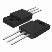
TRIAC 600V 12A TO-220F

BTA212X-600D,127

Manufacturer Part Number
BTA212X-600D,127
Description
TRIAC 600V 12A TO-220F
Manufacturer
NXP Semiconductors
Datasheet

Specifications of BTA212X-600D,127

Package / Case
TO-220-3 Full Pack
Triac Type
Logic - Sensitive Gate
Mounting Type
Through Hole
Configuration
Single
Current - Hold (ih) (max)
15mA
Voltage - Off State
600V
Current - Gate Trigger (igt) (max)
5mA
Current - Non Rep. Surge 50, 60hz (itsm)
95A, 105A
Current - On State (it (rms)) (max)
12A
Voltage - Gate Trigger (vgt) (max)
1.5V
Current - On State (it (rms) (max)
12A
Rated Repetitive Off-state Voltage Vdrm
600 V
Breakover Current Ibo Max
105 A
Off-state Leakage Current @ Vdrm Idrm
0.5 mA
Gate Trigger Voltage (vgt)
1.5 V
Gate Trigger Current (igt)
5 mA
Holding Current (ih Max)
15 mA
Forward Voltage Drop
1.6 V @ 17 A
Mounting Style
SMD/SMT
Repetitive Peak Forward Blocking Voltage
600 V
Lead Free Status / RoHS Status
Lead free / RoHS Compliant
Other names
568-3729
934055321127
BTA212X-600D
Philips Semiconductors
GENERAL DESCRIPTION
Passivated guaranteed commutation
triacs in a full pack, plastic envelope
intended for use in motor control circuits
or with other highly inductive loads.
These
requirements
performance and gate sensitivity. The
"sensitive gate" E series and "logic level"
D series are intended for interfacing with
low power drivers, including micro
controllers.
PINNING - SOT186A
LIMITING VALUES
Limiting values in accordance with the Absolute Maximum System (IEC 134).
1 Although not recommended, off-state voltages up to 800V may be applied without damage, but the triac may
switch to the on-state. The rate of rise of current should not exceed 15 A/ s.
June 2003
Three quadrant triacs
guaranteed commutation
SYMBOL PARAMETER
V
I
I
I
dI
I
P
P
T
T
T(RMS)
TSM
2
GM
case isolated
PIN
t
stg
j
DRM
GM
G(AV)
T
1
2
3
/dt
main terminal 1
main terminal 2
gate
devices
Repetitive peak off-state
voltages
RMS on-state current
Non-repetitive peak
on-state current
I
Repetitive rate of rise of
on-state current after
triggering
Peak gate current
Peak gate power
Average gate power
Storage temperature
Operating junction
temperature
2
t for fusing
DESCRIPTION
of
balance
commutation
the
PIN CONFIGURATION
CONDITIONS
full sine wave;
T
full sine wave;
T
surge
t = 20 ms
t = 16.7 ms
t = 10 ms
I
dI
over any 20 ms
period
TM
hs
j
G
= 25 ˚C prior to
QUICK REFERENCE DATA
/dt = 0.2 A/ s
= 20 A; I
SYMBOL
V
I
I
T(RMS)
TSM
56 ˚C
DRM
G
case
= 0.2 A;
voltages
current
1
1 2 3
PARAMETER
Repetitive peak off-state
RMS on-state current
Non-repetitive peak on-state
MIN.
-40
-
-
-
-
-
-
-
-
-
BTA212X series D, E and F
BTA212X-
BTA212X-
BTA212X-
-600
600
SYMBOL
1
T2
MAX.
105
100
150
125
0.5
12
95
45
2
5
MAX.
Product specification
600D
600E
600F
600
12
95
-800
800
MAX. UNIT
800E
800
12
95
-
-
Rev 3.000
UNIT
G
A/ s
T1
A
˚C
˚C
W
W
V
A
A
A
A
V
A
A
2
s

Related parts for BTA212X-600D,127

BTA212X-600D,127 Summary of contents

Page 1

... T 56 ˚C hs full sine wave ˚C prior to j surge 16 0 / over any period - Product specification BTA212X series D, E and F MAX. MAX. UNIT BTA212X- 600D - BTA212X- 600E 800E BTA212X- 600F - 600 800 SYMBOL T2 MAX. -600 -800 1 600 800 12 95 105 45 100 ...

Page 2

... CONDITIONS BTA212X 0 T2+ G+ T2 T2+ G+ T2 400 0 125 ˚ 125 ˚C D DRM(max Product specification BTA212X series D, E and F MIN. TYP. MAX 2500 - 10 - MIN. TYP. MAX 4 5 MIN. MAX. ...D ...E ... ...

Page 3

... PARAMETER dV /dt Critical rate of rise of D off-state voltage dI /dt Critical rate of change of com commutating current dI /dt Critical rate of change of com commutating current June 2003 BTA212X series D, E and F CONDITIONS BTA212X- ... 67 DRM(max 110 ˚C; exponential j waveform; gate open circuit V = 400 125 ˚C; ...

Page 4

... T 10ms 100ms Fig.5. Maximum permissible repetitive rms on-state , for current I p 20ms TSM T time Tj initial = 25 C max 100 1000 Product specification BTA212X series D, E and F BT138X IT(RMS - Ths / C versus heatsink temperature T IT(RMS 0.01 0.1 1 surge duration / s , versus surge duration, for sinusoidal T(RMS) currents ...

Page 5

... Fig.11. Transient thermal impedance dIcom/dt (A/ms 100 150 (25˚C), Fig.12. Minimum critical rate of change commutating current Product specification BTA212X series D, E and F typ max 0.5 1 1 Zth j-hs (K/W) with heatsink compound without heatsink compound unidirectional bidirectional 0.1ms 1ms 10ms 0.1s 1s ...

Page 6

... Epoxy meets UL94 V0 at 1/8". June 2003 10.3 max 3.2 3.0 2.8 seating 15.8 19 max. max. plane 3 2 2.54 0.5 5.08 6 Product specification BTA212X series D, E and F 4.6 max 2.9 max 6.4 15.8 max 0.6 2.5 1.0 (2x) 0.9 0.7 1.3 Rev 3.000 ...

Page 7

... This data sheet contains data from the product specification. Philips Semiconductors reserves the right to make changes at any time in order to improve the design, manufacturing and supply. Changes will be communicated according to the Customer Product/Process Change Notification (CPCN) procedure SNW-SQ-650A 7 Product specification BTA212X series D, E and F Rev 3.000 ...

Related keywords