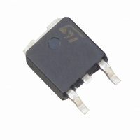
ACS120-7SB-TR STMicroelectronics, ACS120-7SB-TR Datasheet - Page 6

ACS120-7SB-TR
Manufacturer Part Number
ACS120-7SB-TR
Description
IC AC LINE SWITCH D-PAK
Manufacturer
STMicroelectronics
Series
ASD™r
Datasheet
1.ACS120-7SB-TR.pdf
(11 pages)
Specifications of ACS120-7SB-TR
Triac Type
Logic - Sensitive Gate
Mounting Type
Surface Mount
Configuration
Single
Current - Hold (ih) (max)
45mA
Voltage - Off State
700V
Current - Gate Trigger (igt) (max)
10mA
Current - Non Rep. Surge 50, 60hz (itsm)
20A, 11A
Current - On State (it (rms)) (max)
2A
Voltage - Gate Trigger (vgt) (max)
1V
Package / Case
TO-252-3, DPak (2 Leads + Tab), SC-63
Current - On State (it (rms) (max)
2A
Lead Free Status / RoHS Status
Lead free / RoHS Compliant
Other names
497-6099-2
Available stocks
Company
Part Number
Manufacturer
Quantity
Price
Company:
Part Number:
ACS120-7SB-TR/7
Manufacturer:
ST
Quantity:
585
ACS120-7SB/SFP/ST
Fig. 1: Maximum power dissipation versus RMS
on-state current.
6/11
OTHER FIGURES
Maximum power dissipation vs RMS on state current.
RMS on-state current vs ambient temperature, case temperature
Relative variation of thermal impedance junction to ambient vs pulse duration and package
Relative variation of gate trigger current vs junction temperature
Relative variation of holding, latching and gate current vs junction
Relative variation of dV/dt vs Tj
Relative variation of (dV/dt)
Surge peak on-state current vs number of cycles
Non repetitive surge peak on-state current for a sinusoidal pulse with tp<10ms, and corresponding of I²t.
On-state characteristics (maximal values)
Thermal resistance junction to ambient vs copper surface under tab (DPAK)
Relative variation of critical (di/dt)c vs junction temperature
2.4
2.2
2.0
1.8
1.6
1.4
1.2
1.0
0.8
0.6
0.4
0.2
0.0
Fig. 2-2: RMS on-state current versus ambient
temperature.
1.8
1.6
1.4
1.2
1.0
0.8
0.6
0.4
0.2
0.0
0.0
0
P(W)
I
T(RMS)
=180°
0.2
(A)
0.4
25
0.6
0.8
50
T
I
T(RMS)
amb
1.0
(°C)
c
(A)
vs (di/dt)
1.2
75
1.4
Printed circuit board FR4
c
Natural convection
100
1.6
S=0.5cm²
=180°
180°
1.8
125
2.0
Fig. 2-1:
temperature.
2.4
2.2
2.0
1.8
1.6
1.4
1.2
1.0
0.8
0.6
0.4
0.2
0.0
Fig. 3: Relative variation of thermal impedance
versus pulse duration.
1.E+00
1.E-01
1.E-02
0
I
T(RMS)
1.E-02
K=[Zth/Rth]
=180°
DPAK
(A)
25
1.E-01
RMS on-state current versus case
Zth
(j-c)
TO-220FPAB
DPAK
1.E+00
50
Tc(°C)
Zth
t (s)
(j-a)
p
1.E+01
75
TO-220FPAB
1.E+02
TO-220FPAB
100
TO-220AB/DPAK
1.E+03
125


