RH2551000JS03 Vishay, RH2551000JS03 Datasheet
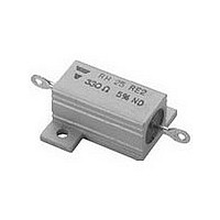
FIXED RESISTORS SFERNICE / RH 25 5K1 5% BA10 E1

RH2551000JS03

Manufacturer Part Number
RH2551000JS03
Description
FIXED RESISTORS SFERNICE / RH 25 5K1 5% BA10 E1
Manufacturer
Vishay
Type
Wirewoundr
Datasheet

Specifications of RH2551000JS03

Power Rating(s)
20W
Resistance
5.1kohm
Tolerance (+ Or -)
5%
Temperature Coefficient
±15
Mounting Style
Flange
Construction
Chassis
Operating Temp Range
-55C to 200C
Case Style
Aluminum Housed
Termination Style
Axial
Military Standard
Not Required
Failure Rate
Not Required
Product Length (mm)
49mm
Product Height (mm)
15mm
Product Depth (mm)
27.5mm
Lead Free Status / RoHS Status
Compliant
RH
Vishay Sfernice
Encased in a compact and light heatsink offering complete environmental protection, great mechanical strength and easy
mounting. Non inductive versions can be supplied under the RHNI designation (please indicate required specifications and
frequency range upon ordering).
NF F 16101, 10/1988 and 16102, 04/1992: Not applicable (our parts contain less than 10 g of combustible materials).
www.vishay.com
104
DIMENSIONS in millimeters
SERIES
RH5
RH10
RH25
RH50
ELECTRICAL SPECIFICATIONS
VISHAY SFERNICE MODEL AND STYLE
NF C 83-210 (CECC 40 203)
POWER RATING
Chassis Mounted Resistors
413 cm
536 cm
Unmounted Resistors
Rated Maximum Voltage (V
2
2
for RH5 and RH10
for RH25 and RH50
28.5 ± 1.5
35.5 ± 1.5
70.2 ± 1.4
49 ± 1.3
A
Heatsink Encased Wirewound Power Resistors
12.5
15.9
19.8
21.4
B ±
0.2
RMS
11.3
18.3
39.7
D ±
0.2
14
)
16.3
E ±
0.5
Vishay Sfernice
Vishay Sfernice
19
28
50
Ø K
For technical questions, contact:
11.1 ± 1.5
6.8 ± 1.5
7.9 ± 1.5
11 ± 1.2
Limits
Limits
Limits
F
MIL
A
D
Q
E
G ± 1
15.5
8.5
11
14
25 °C
70 °C
25 °C
70 °C
25 °C
70 °C
10.7
H ±
0.7
6.2
7.9
9.9
Ø 2
F
RH
16.4
20.6
27.5
29.4
J ±
0.5
Ø P
FEATURES
• 5 W to 50 W at 25 °C
• NF C 83-210
• CECC 40 203
• High stability < 0.05 % year
• Low temperature coefficient typically ± 15 ppm/°C
• Wide range of values from 0.006 Ω to 130 kΩ
• Termination = Sn/Ag/Cu
• Compliant to RoHS directive 2002/95/EC
RH5
J
3.2 W
160 V
10 W
RE4
5 W
4 W
8 W
4 W
sfer@vishay.com
N
Ø K ±
H
0.1
2.4
2.4
3.2
3.2
M
L
MAX.
8.9
11
15
15
L
RH10
12.5 W
4.8 W
250 V
10 W
10 W
RE1
8 W
6 W
G
M ±
0.5
4.3
5.6
8
8
B
N ±
0.3
1.6
2.4
2.4
2
RH25
7.2 W
550 V
MIN.
20 W
16 W
25 W
20 W
Ø P
RE2
2.1
2.1
2.1
2.1
9W
Document Number: 50013
25.3 ± 1.5
30.6 ± 1.5
44.6 ± 1.3
66.5 ± 1.4
Revision: 16-Feb-10
Q
RH50
1285 V
9.6 W
30 W
24 W
50 W
40 W
12 W
RE3
WEIGHT
16.1
28.6
6.4
g
4

Related parts for RH2551000JS03

RH2551000JS03 Summary of contents

Page 1

... RH25 49 ± 1.3 19.8 18.3 28 RH50 70.2 ± 1.4 21.4 39.7 50 ELECTRICAL SPECIFICATIONS VISHAY SFERNICE MODEL AND STYLE NF C 83-210 (CECC 40 203) POWER RATING Chassis Mounted Resistors 2 413 cm for RH5 and RH10 Vishay Sfernice 2 536 cm for RH25 and RH50 Vishay Sfernice ...

Page 2

... The overload voltage shall not be higher than that used for the dielectric strength test (see Standard Electrical Specifications). 2. Short time overload (< 2 s): For times shorter than 2 s, higher overloads can be sustained in some cases. Consult Vishay Sfernice. POWER LOADING 2 ...

Page 3

... Vishay Sfernice POWER RATING 125 100 100 150 200 AMBIENT TEMPERATURE IN °C MARKING Vishay Sfernice trademark, model, style, CECC style (if applicable) nominal resistance (in Ω), tolerance (in %), manufacturing date. ORDERING INFORMATION RH 05 MODEL STYLE NON INDUCTIVE GLOBAL PART NUMBER INFORMATION GLOBAL SIZE OPTION ...

Page 4

... Vishay disclaims any and all liability arising out of the use or application of any product described herein or of any information provided herein to the maximum extent permitted by law. The product specifications do not expand or otherwise modify Vishay’ ...

Related keywords