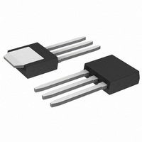
ACS120-7SH STMicroelectronics, ACS120-7SH Datasheet - Page 4

ACS120-7SH
Manufacturer Part Number
ACS120-7SH
Description
IC AC LINE SWITCH IPAK
Manufacturer
STMicroelectronics
Series
ASD™r
Datasheet
1.ACS120-7SB-TR.pdf
(11 pages)
Specifications of ACS120-7SH
Triac Type
Logic - Sensitive Gate
Mounting Type
Through Hole
Configuration
Single
Current - Hold (ih) (max)
45mA
Voltage - Off State
700V
Current - Gate Trigger (igt) (max)
10mA
Current - Non Rep. Surge 50, 60hz (itsm)
20A, 11A
Current - On State (it (rms)) (max)
2A
Voltage - Gate Trigger (vgt) (max)
1V
Package / Case
TO-251-3 Long Leads, IPak, TO-251AB
Current - On State (it (rms) (max)
2A
Lead Free Status / RoHS Status
Lead free / RoHS Compliant
ACS120-7SB/SFP/ST
4/11
AC LINE SWITCH BASIC APPLICATION
The ACS120 device is well adapted to Washing machine, dishwasher, tumble drier, refrigerator,
air-conditioning systems, and cookware. It has been designed especially to switch on & off low power loads
such as solenoid, valve, relay, dispenser, micro-motor, pump, fan and defrost heaters.
Pin COM: Common drive reference to connect to the power line neutral
Pin G: Switch Gate input to connect to the digital controller
Pin OUT: Switch Output to connect to the load
This ACS™ switch is triggered with a negative gate current flowing out of the gate pin G. It can be driven di-
rectly by the digital controller through a resistor as shown on the typical application diagram.
Thanks to its thermal and turn off commutation performances, the ACS120 switch is able to drive with no
turn off additional snubber an inductive load up to 2 A.
TYPICAL APPLICATION DIAGRAM
HIGH INDUCTIVE SWITCH-OFF OPERATION
At the end of the last conduction half-cycle, the load current reaches the holding current level I
ACS™ switch turns off. Because of the inductance L of the load, the current flows then through the ava-
lanche diode D and decreases linearly to zero. During this time, the voltage across the switch is limited to
the clamping voltage V
The energy stored in the inductance of the load depends on the holding current I
to 10 H); it can reach about 10 mJ and is dissipated in the clamping diode section. The ACS switch sustains
the turn off energy because its clamping section is designed for that purpose.
MAINS
L
AC
CL
N
.
- Vcc
COM
D
S
OUT
ON
LOAD
R
L
ACS120
G
ST72 MCU
M
H
and the inductance (up
H
, and the


