5-747909-2 TE Connectivity, 5-747909-2 Datasheet
5-747909-2
Specifications of 5-747909-2
Available stocks


Related parts for 5-747909-2


5-747909-2 Summary of contents
Page 1
... Dia. Holes Sockets (pgs. 100, 101) Clinch Nuts, 4-40 Threaded Dimensions are shown for USA: 1-800-522-6752 reference purposes only. Canada: 1-905-470-4425 Specifications subject Mexico: 01-800-733-8926 to change. C. America: 52-55-1106-0803 Contacts Termination Plating Duplex (.000030 [0.00076] Gold and Tin) Crimp Duplex Posted ...
Page 2
... Values in brackets www.tycoelectronics.com are metric equivalents. (Continued) Section Contents Plug and Receptacle Connectors . . . . . . . . . . . . . . . . . . . . . 92, 93 Basic Shielding Hardware Kits . . . . . . . . . . . . . . . . . . . . . . . . 94, 95 Shielding Hardware Enclosure Kits . . . . . . . . . . . . . . . . . . . 96, 97 Preassembled Shielded Connector Kits . . . . . . . . . . . . . . . . . . 98 Ferrules for Shielding Hardware Kits . . . . . . . . . . . . . . . . . . . . . . 99 Contacts . . . . . . . . . . . . . . . . . . . . . . . . . . . . . . . . . . . . . . . . . . . 100, 101 Application Tooling . . . . . . . . . . . . . . . . . . . . . . . . . . . . . . . . . . . . . . 102 R ...
Page 3
... HDE—pages 110-123 HDP—pages 90-102 HD-20 Board Mount— pages 54-71, 78-85, 87-89 Mating/Panel Mounting—page 42 Cable Clamps—pages 132, 133, 135-137, 140, 141, 144, 145 Mating Hardware—pages 146-150, 153, 155 Technical Documents: Product Specification—108-40005 Application Specifications— ...
Page 4
... Standard 1658641-3 1658641-1 94V-0 Clinch Nut — — Dimensions are shown for USA: 1-800-522-6752 reference purposes only. Canada: 1-905-470-4425 Specifications subject Mexico: 01-800-733-8926 to change. C. America: 52-55-1106-0803 (Continued) .243 [6.17] Receptacle Part Nos. Zinc Tin With Plated Plated Grounding Shell Shell Indents ...
Page 5
... Contacts—pages 100, 101 Application Tooling—page 102 Mateable Connectors: HDE—pages 110-123 HDP—pages 90-102 HD-20 Board Mount— pages 54-71, 78-85, 87-89 Mating/Panel Mounting—page 42 Mating Hardware—pages 146-150, 153, 155 Ferrules—page 99 Technical Documents: Product Specifications— ...
Page 6
... Be Purchased Separately) View of Rear Shell (With Shields Removed) Plug Kit Numbers Receptacle Kit Numbers 1658645-1 1658646-1 5748526-1 5748536-1 1658647-1 5747539-1 5750636-1 5787908-1 1658648-1 1658649-1 — 1658662-1 1658650-1 1658651-1 5786929-1 — 1658652-1 1658653-1 South America: 55-11-2103-6000 Hong Kong: 852-2735-1628 Japan: 81-44-844-8013 UK: 44-8706-080-208 95 ...
Page 7
... Contacts—pages 100, 101 Application Tooling—page 102 Mateable Connectors: HDE—pages 110-123 HDP—pages 90-102 HD-20 Board Mount— pages 54-71, 78-85, 87-89 Mating/Panel Mounting—page 42 Mating Hardware—pages 146-150, 153, 155 Ferrules—page 99 Technical Documents: Product Specifications— ...
Page 8
... Dimensions are shown for USA: 1-800-522-6752 reference purposes only. Canada: 1-905-470-4425 Specifications subject Mexico: 01-800-733-8926 to change. C. America: 52-55-1106-0803 (Continued) F Max Cable Ref. D Max. 1.467 [37.26] Typ. Shielding Enclosure Kit Numbers Expansion Tool Receptacle ...
Page 9
... Enclosures—Elastomer, styrene poly- tional information call the Tooling olefin, or PVC, black Assistance Center: 1-800-722-1111. Shields and Shells—Carbon steel per ASTM A109, plated with .000200 [0.00508] min. tin over .000050 [0.00127] min. copper Related Product Data: Contact Arrangements—page 40 Performance Characteristics— page 41 Contacts— ...
Page 10
... Straight 2-747580-2 15.88 12.19-14.28 *Die sets used with Hand Crimping Tool Part No. 543344-1 or Pneumatic Bench Tool Part No. 312522-3 equipped with Die Set Holder Part No. 58449-1. Bench Mounting Plate Part No. 313183-1 Pneumatic Bench Tool No. 312522-3 (Requires Die Set Holder No. 58449-1.) [8.38])† ...
Page 11
... Dimensions are shown for USA: 1-800-522-6752 reference purposes only. Canada: 1-905-470-4425 Specifications subject Mexico: 01-800-733-8926 to change. C. America: 52-55-1106-0803 Socket Hand Tools for Loose Form Contacts CERTI-CRIMP II Applicators* Socket PRO-CRIMPER II Hand Tool for Strip Form Hand Tool (Color Code) ...
Page 12
... Stabilizer Pin Loose Form Contact Numbers .125 [3.18] .188 [4.78] Post Length* Post Length* Pin Socket Pin Socket — 5-745288-5 5-745287-4 7-745288-0 4-745287-7 5-745288-8 5-745287-0 6-745288-1 — — — — Pin Strip Form Loose Form Contact Number Socket Pin 66569-2 66570-3 ...
Page 13
... AWG [0. requirement is single-phase solid. Production rates 220 VAC Hz range up to 4800 leads per For further information hour for 3 [76.2] lengths. request Catalog 124324. The machine is micropro- cessor controlled, and pro - grammed and operated with ...
Page 14
... Socket [3.05] (pg. 109) Dia. Holes Dimensions are shown for USA: 1-800-522-6752 reference purposes only. Canada: 1-905-470-4425 Specifications subject Mexico: 01-800-733-8926 to change. C. America: 52-55-1106-0803 Contacts Plating Duplex (.000030 [0.00076] Gold and Tin) Crimp Duplex (Gold Flash and Tin) ➧ ➧ ...
Page 15
... Revised 1-08 millimeters unless otherwise specified. Values in brackets www.tycoelectronics.com are metric equivalents. Section Contents Plug and Receptacle Connectors . . . . . . . . . . . . . . . . . . . . . . . 105 Basic Shielding Hardware Kits . . . . . . . . . . . . . . . . . . . . . . . . . . 106 Shielding Hardware Enclosure Kits . . . . . . . . . . . . . . . . . . . . . . 107 Ferrules for Shielding Hardware Kits . . . . . . . . . . . . . . . . . . . . 108 Contacts 109 Application Tooling . . . . . . . . . . . . . . . . . . . . . . . . . . . . . . . . . 108, 109 ...
Page 16
... Related Product Data: Contact Arrangements—page 40 Performance Characteristics— page 41 Contacts—page 109 Ferrules—page 108 Mating/Panel Mounting —page 42 Cable Clamps—pages 132, 133, 135- 137, 140, 141, 144, 145 Mating Hardware—pages 146-150, 153, 155 No. of Technical Documents: Shell Contact ...
Page 17
... Performance Characteristics— page 41 Contacts—page 109 Ferrules—page 108 Application Tooling—pages 108 & 109 Mateable Connectors— Shell pages 105 & 107 Size Mating Hardware—pages 146-150, 153, 155 Mating/Panel Mounting—page 42 Technical Documents: Application Specifications— 114-10001 Product Specification—108-1268 Instruction Sheet— ...
Page 18
... Contact Arrangements—page 40 Performance Characteristics— page 41 Contacts—page 109 Ferrules—page 108 Application Tooling—pages 108 & 109 Mateable Connectors— Shell Contact pages 105 & 106 Size Positions Mating Hardware—pages 146-150, 153-155 1 Mating/Panel Mounting—page 42 2 Technical Documents: 3 Application Specifications— ...
Page 19
... Straight 15.88 12.19-14.28 *Die sets used with Hand Crimping Tool Part No. 543344-1 or Pneumatic Bench Tool Part No. 312522-3 equipped with Die Set Holder Part No. 58449-1. Bench Mounting Plate Part No. 313183-1 Pneumatic Bench Tool No. 312522-3 (Requires Die Set Holder No ...
Page 20
... AMP Crimp Quality Monitor, precision adjustment for crimp for measuring the crimp height height. Power requirement is of each termina tion 120 or 220 VAC Hz. made, plus evalu ating the For further information, request quality of each crimp. Catalog 65828. For further information, request Catalog 65404 ...
Page 21
... Flash snap-in contacts and Tin) available, see page 121 ➧ ➧ Duplex (.000030 [0.00076] Gold and Insulation Tin) Displacement Duplex * Interchangeable crimp (Gold Flash snap-in contacts and Tin) available, see page 121 South America: 55-11-2103-6000 Hong Kong: 852-2735-1628 Japan: 81-44-844-8013 UK: 44-8706-080-208 ...
Page 22
... Association, File No. 1088108 (LR 7189-207) Typical Application Rates Tool Pistol Style Arbor Tool CHAMPOMATOR Machine Note: Rates are based on total time to complete a double ended 25 position Jacketed Cable Assembly Shielded Cable Unshielded Clamps and Cable Clamps Shielding Hardware and Enclosure Kits Straight Exit ...
Page 23
... Individual conductor strands should be larger than .005 inch [0.127] diameter. 4. Extraction Tool Part No. 91232-1 (Instruction Sheet 408-6631) is used to remove pin or socket contacts. 5. For terminating more than one wire drain wire, use crimp contacts on page 121. Dimensions are shown for USA: 1-800-522-6752 reference purposes only ...
Page 24
... Individual conductor strands should be larger than .005 inch [0.127] diameter. 4. Extraction Tool Part No. 91232-1 (Instruction Sheet 408-6631) is used to remove pin or socket contacts. 5. For terminating more than one wire drain wire, use crimp contacts on page 121. Note: All part numbers are RoHS compliant. ...
Page 25
... HDE connectors are designed for terminating solid or stranded (7-strand max.) wire. 4. Individual conductor strands should be larger than .005 inch [0.127] diameter. 5. Extraction Tool Part No. 91232-1 (Instruction Sheet 408-6631) is used to remove pin or socket contacts. 6. For terminating more than one wire drain wire, use crimp contacts on page 121. ...
Page 26
... HDE connectors are designed for terminating solid or stranded (7-strand max.) wire. 4. Individual conductor strands should be larger than .005 inch [0.127] diameter. 5. Extraction Tool Part No. 91232-1 (Instruction Sheet 408-6631) is used to remove pin or socket contacts. 6. For terminating more than one wire drain wire, use crimp contacts on page 121. ...
Page 27
... Application Specifications— Application Tooling—pages 121-123 114-40002 114-40003 Mateable Connectors: 114-40006 HDP—pages 90-97 HD-20 Board Mount—pages 54-71, Instruction Sheet—408-9010 78-85, 87-89 Note: Instruction Sheets for Mating Hardware—pages 146-150, Tyco Electronics Tooling are packaged 153, 155 with the tooling. For additional informa- Mating/Panel Mounting— ...
Page 28
... Application Tooling—pages 121-123 114-40003 Mateable Connectors: 114-40006 HDP—pages 90-97 Instruction Sheet—408-9010 HD-20 Board Mount—pages 54-71, 78-85, 87-89 Note: Instruction Sheets for Tyco Electronics Tooling are packaged Mating Hardware—pages 146-150, with the tooling. For additional informa- 153, 155 tion call the Tooling Assistance Center: Mating/Panel Mounting— ...
Page 29
... Application Tooling—pages 121-123 114-40006 Mateable Connectors: 114-40008 HDP—pages 90-97 Instruction Sheet—408-9172 HD-20 Board Mount—pages 54-71, Note: Instruction Sheets for 78-85, 87-89 Tyco Electronics Tooling are packaged Mating Hardware—pages 146-150, with the tooling. For additional informa- 153, 155 tion call the Tooling Assistance Center: Mating/Panel Mounting— ...
Page 30
... Application Tooling—pages 121-123 114-40006 Mateable Connectors: 114-40008 HDP—pages 90-97 Instruction Sheet—408-9172 HD-20 Board Mount—pages 54-71, Note: Instruction Sheets for 78-85, 87-89 Tyco Electronics Tooling are packaged Mating Hardware—pages 146-150, with the tooling. For additional informa- 153, 155 tion call the Tooling Assistance Center: Mating/Panel Mounting— ...
Page 31
... Straight 15.88 12.19-14.28 *Die sets used with Hand Crimping Tool Part No. 543344-1 or Pneumatic Bench Tool Part No. 312522-3 equipped with Die Set Holder Part No. 58449-1. Bench Mounting Plate Part No. 313183-1 Pneumatic Bench Tool No. 312522-3 (Requires Die Set Holder No ...
Page 32
... B A .075 .054 3 1.91 1.37 B Dimensions are shown for USA: 1-800-522-6752 reference purposes only. Canada: 1-905-470-4425 Specifications subject Mexico: 01-800-733-8926 to change. C. America: 52-55-1106-0803 Socket Contact Part Numbers Pin Socket Strip Form Strip Form — 1-745269-1 1-745266-0 1-745269-0 1-745267-0 1-745270-1 — 1-745270-0 ...
Page 33
... Canada: 1-905-470-4425 Specifications subject Mexico: 01-800-733-8926 to change. C. America: 52-55-1106-0803 Air Pistol Grip Tool Handle No. 58075-1 Head Assembly No. 58063-2 Air actuated, utilizing modular heads. Bench Mount Electric Power Assembly Head Assembly No. 58063-2 This tool electrically powered and actuated by a foot switch. South America: 55-11-2103-6000 ...
Page 34
... No. 852423-1 Manual Arbor Tool Wire O.D. .041-.060 [1.04-1.52]—No. 543157-1 (tool mount), Wire O.D. .040 [1.02] and smaller—No. 543157-1 (tool mount), Note: All part numbers are RoHS compliant. Catalog 82068 Dimensions are in inches and Revised 1-08 millimeters unless otherwise specified ...
Page 35
... Contacts—Phosphor bronze, duplex CSA Certified in File ■ plated .000030 [0.00076] min. gold on R No.164196 (LR 7189) mating end, .000100-.000200 [0.00254- 0.00508] bright tin on termination end ■ UL Listed in File No. with entire contact underplated .000050 E81956, evaluated to [0.00127] min. nickel requirements found in UL ...
Page 36
... Contact Arrangement—page 40 Performance Characteristics— page 41 No. of Mateable Receptacles: Contact HDF-20 All-Plastic—page 124 Pos. & (Shell Size) HD-20 Board Mount—pages 54-71, 78-85, 87-89 9 (1) HDE All-Plastic—pages 147, 148 15 (2) Mating/Panel Mounting—page 126 25 (3) Ribbon Cable—page 125 37 (4) Accessories: Note: All assemblies are supplied with housing and cover pre-assembled ...
Page 37
... HDF-20 Plugs/Receptacles Mating and Panel Mounting Specifications Plug/Receptacle Mating Panel Cutouts .265 ±.015 ] Shell Sizes 1 & 2 [6.73 ±0.38 .256 ±.015 ] Shell Sizes 3, 4 & 5 [6.50 ±0.38 Plug Receptacle The .265/.256 [6.73/6.50] dimensions are required to assure full mating of connector halves. These dimensions must be taken ...
Page 38
... Consists of a hand tool frame, a universal base assembly, a bench mount kit, and connector-specific tooling for AMP-LATCH Standard and Novo Receptacles, Card-Edge Connectors, and AMPLIMITE HDF-20 Connectors. Note: For 50-position HDF connec- tors, you must also order Connector- Specific Kit No. 768350-1. Dimensions are shown for USA: 1-800-522-6752 reference purposes only ...
Page 39
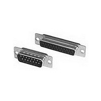
... Two-piece 94V-0 rated plastic insert ■ Anti-solderwicking contact design Intermateable with other ■ subminiature D connectors ■ Available in 9, 15, 25 and 37 position (shell sizes 1-4) plugs and receptacles Easy application without ■ special application tools ■ Shields offer full EMI shielding and ESD insulation ■ ...
Page 40
... Ref. [1.20] Typ. Receptacle Part Numbers Zinc Plated Tin Plated Zinc Plated Shell Shell Shell 5-747904-2 5-747905-2 5-747905-2 5-747908-2 5-747909-2 5-747909-2 5-747912-2 5-747913-2 5-747913-2 5-747916-2 5-747917-2 747917-4 South America: 55-11-2103-6000 Hong Kong: 852-2735-1628 Japan: 81-44-844-8013 UK: 44-8706-080-208 129 ...
Page 41
... Assembled Tooling: Part Number 1571750-1 Individual Tools (for customer fabrication): 1571749-1 & 1571749-2 Dimensions are shown for USA: 1-800-522-6752 reference purposes only. Canada: 1-905-470-4425 Specifications subject Mexico: 01-800-733-8926 to change. C. America: 52-55-1106-0803 ...
Page 42
... Male Screw Retainers for Metal-Shell and All-Plastic Connectors (HDF 147 Female Screwlocks for Metal-Shell and All-Plastic Connectors (HDE, HDF, HDP 148 Slide Latches 149, 150 Slide Latch Clips . . . . . . . . . . . . . . . . . . . . . . . . . . . . . . . . . . . . . . . . 151 Locking Post Assemblies . . . . . . . . . . . . . . . . . . . . . . . . . . . . . . . . 151 Spring Latches (Two-Piece 152 Latching Blocks (HDE, HDF, HDP, HD 153, 154 Standoff Bushings ...
Page 43
... Steel, zinc plated HDE or HDP Plug or receptacle Related Product Data: (Shown for Ref. only) Connectors used with: HDE Metal-Shell—pages 114 & 115 HDP Metal-Shell—pages 90-102 Other accessory capabilities: Spring Latches (Two Piece)— page 152 Technical Documents: Instruction Sheet—408-9238 Material and Finish: Straight/90° ...
Page 44
... Screws—Carbon steel, zinc plated Cable Gate—Polypropylene, Black Related Product Data: Connectors used with: HDP Metal-Shell—pages 90-102 HDE All-Plastic—pages 112 & 113 HDE Metal-Shell—pages 114 & 115 Technical Documents: Instruction Sheet—408-7837 Instruction Sheet—408-9544 Shell Size ...
Page 45
... Self Tapping Screws—Steel, zinc plated Contacts—Brass (HDP Pins), Phosphor Bronze (All Others), plated gold flash on the mating end, .000100 [0.00254] min. tin or tin on the terminating end, all over .000030 [0.00076] min. nickel underplating Housing—Polyester or nylon, glass- filled, UL rated 94V-0, black Shell— ...
Page 46
... Material Black thermoplastic Related Product Data: Shell Size Connectors used with: HDE All-Plastic—pages 112 & 113 HDE Metal-Shell—pages 114 & 115 1 Other accessory capabilities: 2 Male Screw Retainers— pages 146 & 147 3 Female Screwlocks—page 148 Locking Posts and Slide Latches— ...
Page 47
... Slide-On Back Covers Black thermoplastic Related Product Data: Connectors used with: HDE All-Plastic—pages 112 & 113 HDE Metal-Shell—pages 114 & 115 Other accessory capabilities: RFI/EMI Metal Shields— pages 141 & 142 Male Screw Retainers— pages 146 & 147 Locking Posts and Slide Latches— ...
Page 48
... Cable Gates are inter- changeable allowing Typical Cable Support 90° and 180° cable Gate (Supplied with exit. Blank gate shown Cable Clamp Kit) in 90° exit. Shell Size 3 & 4 & 5 Cable Clamp Kit No. Individual Bulk Packed* .160 207467-1 207467-2 4.06 ...
Page 49
... Screw Retainers, Female Screw-locks or Spring Latches and Latching Blocks. Their hinged construction allows easy assembly to a harness. Also, the straight or 45° angle of the cable exit is achieved by merely positioning the Cable Support Gate for the desired angle prior to installing the assembly onto the plug or receptacle ...
Page 50
... Spring Latch (Two-Piece)— page 152 Notes: 1. All parts are packaged unassembled. 2. Jackscrews must be purchased separately. 3. Split-ring and crimp ferrules are shown on pages 143-145. Technical Documents: 4. Shielded cable clamps will not accept connector housings with clinch nuts. Instruction Sheet—408-6609 Note: All part numbers are RoHS compliant. ...
Page 51
... Material Black thermoplastic Related Product Data: Connectors used with: HDE All-Plastic—pages 112 & 113 HDE Metal-Shell—pages 114 & 115 HDP Metal-Shell—pages 90-102 Other accessory capabilities: Female Screwlocks—page 148 Locking Posts and Slide Latches— pages 149-151 Latching Blocks— ...
Page 52
... Notes: 1. All parts are packaged unassembled. 2. Jackscrews must be purchased separately. Note: All part numbers are RoHS 3. Split-ring and crimp ferrules are shown on pages 143-145. compliant. 4. Shielded cable clamps will not accept connector housings with clinch nuts. Catalog 82068 Dimensions are in inches and ...
Page 53
... Jacketed Cable 108-40032 (Two-Piece) Instruction Sheet—408-6769 Shell Size * Cable Dia. with Grommet Kit: Size 2 = .185-.320 [4.70-8.13]; Size 3 = .255-.470 [6.48-11.94]. Notes: 1. All parts are packaged unassembled. Note: All part numbers are RoHS compliant. 142 Catalog 82068 Dimensions are in inches and ...
Page 54
... Outer Ferrule Cable Jacket Inner Ferrule Flared Braid Conductors Pneumatic Bench Tool (See pages 144 & 145 for Hand Tool No. 312522-2 (Requires Die Set Holder No. 58449-1.) Cable Jacket Split-Ring Ferrule Foil or Braid (to be folded back over ferrule and ...
Page 55
... Min. O.D. is .040 [1.02] smaller than Max. O.D. **For inner and outer ferrules, Min. O.D. is .050 [1.27] smaller than Max. O.D. At the Max. cable O.D. the Min. insulation thickness is .060 [1.52]. Note: All part numbers are RoHS compliant. ...
Page 56
... Min. O.D. is .040 [1.02] smaller than Max. O.D. **For inner and outer ferrules, Min. O.D. is .050 [1.27] smaller than Max. O.D. At the Max. cable O.D. the Min. insulation thickness is .060 [1.52]. Note: Refer to page 143 for Application Tooling for ferrules. ...
Page 57
... Retaining clip must be assembled onto connector flanges with threaded hole toward wire side of connector. 5. All screws have straight slotted heads except where noted. 6. Retaining clip must be assembled onto connector flanges with notched side of retainer toward mating side of connector. ...
Page 58
... Each kit is comprised of two 4-40 male screws and two retaining clips. 3. Male screw retainers mate with female screwlocks (page 148), with HDF All-Plastic connectors featuring 4-40 threaded inserts (page 125), with HD All-Plastic board mount connectors featuring integral standoffs with 4-40 threaded inserts and female screwlocks. ...
Page 59
... Integral Standoffs 2. Each female screwlock kit is comprised of two assemblies as illustrated above. 3. One or two flat washers may be required for panel thicknesses less than .060 [1.52]. Female screwlocks are not recommended for panel thicknesses greater than .060 [1.52]. 4. Female screwlocks with 2-56 thread size are to be used with cable clamps with mounting flanges. Female screwlocks with 4-40 and M3 (Metric) thread sizes can be used with all other cable clamps ...
Page 60
... Metal-Shell or .135 All-Plastic [3.43] Plug or Receptacle (Shown for Ref. only) A Lock Washer Hex Nut (2 Supplied) (2 Supplied) For Shell Sizes 2, 3 and 5 Style III Slide Latch .135 (See Note 5.) [3.43] Plug or Receptacle (Shown for Ref. only) Flat Washer (2 Supplied) Lock Washer (2 Supplied) ...
Page 61
... Style II slide latches can be used with any cable clamp that has the mounting ear configuration as shown above. 5. Style III slide latches can be used on connectors without cable clamps or with cable clamps that do not have the mounting ear configuration shown with Style II above. ...
Page 62
... Locking posts with 4-40 thread size can be used with all other cable clamps 5. Locking posts mate with slide latches (page 149). South America: 55-11-2103-6000 Hong Kong: 852-2735-1628 Japan: 81-44-844-8013 UK: 44-8706-080-208 ...
Page 63
... Notes: 1. Two-piece spring latches can be used with RFI/EMI shields (pages 141). Notes: 2. Two-piece spring latches mate with latch- ing blocks (pages 153 & 154). A .920 [23.37] Typical Application of Two-Piece Spring Latches with Post Molded Strain Relief .170 [4.32] Min. ...
Page 64
... Each front panel latching block kit is comprised of two latching blocks. Two pan head screws of the appropriate length and thread size to be supplied by customer. Notes dimension .250 [6.35] is for connector flange mounting, .220 [5.59] is for use with .030 [0.76] thick panels, and .190 [4.83] is for use with .060 [1.52] thick panels. Notes: 4 ...
Page 65
... These latching blocks allow mounting screws to be installed thru the front of the block and to be screwed into the bracket of a right-angle connector, a fixed insert in a connector mounting flange nut behind the connector mounting flange (as illustrated above). 3. Latching blocks mate with spring latches (page 152). Typical Application of Rear-Panel Mounted Subminiature D Connector using Rear-Panel Latching Blocks ...
Page 66
... Metal-Shell or All-Plastic Receptacle (Shown for Ref. only) A .400 [10.16] .120 Dia. [3.05] (2 Holes ± .010 C [± 0.25 ] .010 [0.25] Ref. 9, 15, 25 and 37 Positions Dimensions A B .746 .984 18.95 24.99 1.074 1.312 27.28 33.32 1.614 1.852 41.00 47.04 2.266 2.500 57.56 63.50 ...