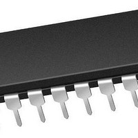
PIC16F1829-E/P Microchip Technology, PIC16F1829-E/P Datasheet - Page 17

PIC16F1829-E/P
Manufacturer Part Number
PIC16F1829-E/P
Description
14 KB Flash, 1K Bytes RAM, 32 MHz Int. Osc, 18 I/0, Enhanced Mid Range Core 20 P
Manufacturer
Microchip Technology
Series
PIC® XLP™ mTouch™ 16Fr
Datasheet
1.PIC16LF1829-ISO.pdf
(420 pages)
Specifications of PIC16F1829-E/P
Core Processor
PIC
Core Size
8-Bit
Speed
32MHz
Connectivity
I²C, LIN, SPI, UART/USART
Peripherals
Brown-out Detect/Reset, POR, PWM, WDT
Number Of I /o
17
Program Memory Size
14KB (8K x 14)
Program Memory Type
FLASH
Eeprom Size
256 x 8
Ram Size
1K x 8
Voltage - Supply (vcc/vdd)
1.8 V ~ 5.5 V
Data Converters
A/D 12x10b
Oscillator Type
Internal
Operating Temperature
-40°C ~ 125°C
Package / Case
*
Processor Series
PIC16F182x
Core
PIC
Data Bus Width
8 bit
Data Ram Size
1 KB
Interface Type
I2C, SPI, USART
Maximum Clock Frequency
32 MHz
Number Of Programmable I/os
18
Number Of Timers
5
Operating Supply Voltage
1.8 V to 5.5 V
Maximum Operating Temperature
+ 125 C
Mounting Style
Through Hole
Lead Free Status / RoHS Status
Lead free / RoHS Compliant
Lead Free Status / RoHS Status
Lead free / RoHS Compliant
- Current page: 17 of 420
- Download datasheet (5Mb)
TABLE 1-2:
2010 Microchip Technology Inc.
RC3/AN7/CPS7/C12IN3-/
P2A
SS1
RC4/C2OUT/SRNQ/P1B/TX
CK
RC5/P1A/CCP1/DT
MDCIN2
V
V
Legend: AN = Analog input or output CMOS = CMOS compatible input or output
Note 1: Pin functions can be moved using the APFCON0 or APFCON1 register.
DD
SS
(1,2)
(1,2)
(1,2)
2: Default function location.
/MDOUT
/CCP2
/MDMIN
TTL = TTL compatible input
HV = High Voltage
Name
(1,2)
/P1C
PIC16F/LF1825 PINOUT DESCRIPTION (CONTINUED)
(1,2)
(1,2)
/RX
/
(1,2)
(1,2)
/
/
Function
MDCIN2
C12IN3-
MDOUT
MDMIN
C2OUT
SRNQ
CPS7
CCP2
CCP1
RC3
RC4
RC5
AN7
P2A
P1C
SS1
P1B
P1A
V
V
CK
RX
TX
DT
DD
SS
ST
XTAL = Crystal
Power
Power
Input
Type
= Schmitt Trigger input with CMOS levels I
TTL
TTL
TTL
AN
AN
AN
AN
ST
ST
ST
ST
ST
ST
ST
—
—
—
—
—
—
—
—
Output
Preliminary
CMOS General purpose I/O.
CMOS PWM output.
CMOS PWM output.
CMOS General purpose I/O.
CMOS Comparator C2 output.
CMOS SR Latch inverting output.
CMOS PWM output.
CMOS USART asynchronous transmit.
CMOS USART synchronous clock.
CMOS Modulator output.
CMOS General purpose I/O.
CMOS PWM output.
CMOS Capture/Compare/PWM 1.
CMOS USART synchronous data.
Type
—
—
—
—
—
—
—
—
—
—
A/D Channel 7 input.
Capacitive sensing input 7.
Comparator C1 or C2 negative input.
Capacitive sensing input 2.
Slave Select input.
Modulator source input.
USART asynchronous input.
Modulator Carrier Input 2.
Positive supply.
Ground reference.
PIC16F/LF1825/1829
Description
OD
2
C™ = Schmitt Trigger input with I
= Open Drain
levels
DS41440A-page 17
2
C
Related parts for PIC16F1829-E/P
Image
Part Number
Description
Manufacturer
Datasheet
Request
R

Part Number:
Description:
IC, 8BIT MCU, PIC16F, 32MHZ, SOIC-18
Manufacturer:
Microchip Technology
Datasheet:

Part Number:
Description:
IC, 8BIT MCU, PIC16F, 32MHZ, SSOP-20
Manufacturer:
Microchip Technology
Datasheet:

Part Number:
Description:
IC, 8BIT MCU, PIC16F, 32MHZ, DIP-18
Manufacturer:
Microchip Technology
Datasheet:

Part Number:
Description:
IC, 8BIT MCU, PIC16F, 32MHZ, QFN-28
Manufacturer:
Microchip Technology
Datasheet:

Part Number:
Description:
IC, 8BIT MCU, PIC16F, 32MHZ, QFN-28
Manufacturer:
Microchip Technology
Datasheet:

Part Number:
Description:
IC, 8BIT MCU, PIC16F, 32MHZ, QFN-28
Manufacturer:
Microchip Technology
Datasheet:

Part Number:
Description:
IC, 8BIT MCU, PIC16F, 32MHZ, SSOP-20
Manufacturer:
Microchip Technology
Datasheet:

Part Number:
Description:
IC, 8BIT MCU, PIC16F, 20MHZ, DIP-40
Manufacturer:
Microchip Technology
Datasheet:

Part Number:
Description:
IC, 8BIT MCU, PIC16F, 32MHZ, QFN-28
Manufacturer:
Microchip Technology
Datasheet:

Part Number:
Description:
IC, 8BIT MCU, PIC16F, 20MHZ, MQFP-44
Manufacturer:
Microchip Technology
Datasheet:

Part Number:
Description:
IC, 8BIT MCU, PIC16F, 20MHZ, QFN-20
Manufacturer:
Microchip Technology
Datasheet:

Part Number:
Description:
IC, 8BIT MCU, PIC16F, 32MHZ, QFN-28
Manufacturer:
Microchip Technology
Datasheet:

Part Number:
Description:
MCU 14KB FLASH 768B RAM 64-TQFP
Manufacturer:
Microchip Technology
Datasheet:

Part Number:
Description:
7 KB Flash, 384 Bytes RAM, 32 MHz Int. Osc, 16 I/0, Enhanced Mid Range Core, Low
Manufacturer:
Microchip Technology

Part Number:
Description:
14KB Flash, 512B RAM, 256B EEPROM, LCD, 1.8-5.5V 40 UQFN 5x5x0.5mm TUBE
Manufacturer:
Microchip Technology
Datasheet:


