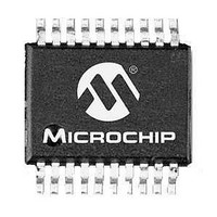
PIC16LF1507-E/SO Microchip Technology, PIC16LF1507-E/SO Datasheet - Page 259

PIC16LF1507-E/SO
Manufacturer Part Number
PIC16LF1507-E/SO
Description
3.5KB Flash, 128B RAM, 18 I/O, CLC, CWG, DDS, 10-bit ADC 20 SOIC .300in TUBE
Manufacturer
Microchip Technology
Series
PIC® 16Fr
Datasheet
1.PIC16F1507-EML.pdf
(266 pages)
Specifications of PIC16LF1507-E/SO
Processor Series
PIC16
Core
PIC16F
Data Bus Width
8 bit
Program Memory Type
Flash
Program Memory Size
3.5 KB
Data Ram Size
128 B
Interface Type
ICSP
Maximum Clock Frequency
20 MHz
Number Of Programmable I/os
18
Number Of Timers
3
Operating Supply Voltage
2.3 V to 5.5 V
Maximum Operating Temperature
+ 125 C
Mounting Style
SMD/SMT
Package / Case
SOIC-20
Minimum Operating Temperature
- 40 C
Operating Temperature Range
- 40 C to + 125 C
Supply Current (max)
30 uA
Core Processor
PIC
Core Size
8-Bit
Speed
20MHz
Connectivity
-
Peripherals
Brown-out Detect/Reset, POR, PWM, WDT
Number Of I /o
17
Eeprom Size
-
Ram Size
128 x 8
Voltage - Supply (vcc/vdd)
1.8 V ~ 3.6 V
Data Converters
A/D 12x10b
Oscillator Type
Internal
Operating Temperature
-40°C ~ 125°C
Lead Free Status / Rohs Status
Details
PIC16(L)F1507
MPLINK Object Linker/MPLIB Object Librarian ................ 242
N
NCO
NCOxACCH Register........................................................ 184
NCOxACCL Register ........................................................ 184
NCOxACCU Register........................................................ 184
NCOxCLK Register ........................................................... 183
NCOxCON Register .......................................................... 183
NCOxINCH Register ......................................................... 185
NCOxINCL Register.......................................................... 185
Numerically Controlled Oscillator (NCO)........................... 177
O
OPCODE Field Descriptions ............................................. 207
OPTION ............................................................................ 217
OPTION Register .............................................................. 137
OSCCON Register .............................................................. 51
Oscillator
Oscillator Module ................................................................ 45
Oscillator Parameters........................................................ 232
Oscillator Specifications .................................................... 232
Oscillator Start-up Timer (OST)
OSCSTAT Register............................................................. 52
P
Packaging ......................................................................... 245
PCL and PCLATH ............................................................... 14
PCL Register....................................................................... 24
PCLATH Register................................................................ 24
PCON Register ............................................................. 25, 59
PIE1 Register ................................................................ 25, 67
PIE2 Register ................................................................ 25, 68
PIE3 Register ................................................................ 25, 69
Pinout Descriptions
PIR1 Register................................................................ 25, 70
PIR2 Register................................................................ 25, 71
PIR3 Register................................................................ 25, 72
PMADR Registers ............................................................... 83
PMADRH Registers ............................................................ 83
PMADRL Register............................................................... 96
PMADRL Registers ............................................................. 83
PMCON1 Register ........................................................ 83, 97
PMCON2 Register ........................................................ 83, 98
PMDATH Register............................................................... 96
PMDATL Register ............................................................... 96
PMDRH Register................................................................. 96
PORTA.............................................................................. 101
PORTA Register ............................................................... 102
DS41586A-page 259
Associated registers.................................................. 186
Associated Registers .................................................. 52
Associated registers.................................................. 201
ECH ............................................................................ 45
ECL ............................................................................. 45
ECM ............................................................................ 45
INTOSC ...................................................................... 45
Specifications ............................................................ 235
Marking ............................................................. 245, 246
PDIP Details.............................................................. 247
PIC16(L)F1507 ........................................................... 11
ANSELA Register ..................................................... 101
Associated Registers ................................................ 104
Configuration Word w/ PORTA ................................. 104
LATA Register............................................................. 26
PORTA Register ......................................................... 25
Specifications ............................................................ 233
Preliminary
PORTB
PORTB Register ............................................................... 106
PORTC
PORTC Register............................................................... 109
Power-Down Mode (Sleep)................................................. 75
Power-on Reset .................................................................. 54
Power-up Time-out Sequence ............................................ 56
Power-up Timer (PWRT) .................................................... 54
PR2 Register ...................................................................... 25
Program Memory ................................................................ 15
Programming, Device Instructions .................................... 207
Pulse Width Modulation (PWM)........................................ 155
PWMxCON Register ......................................................... 159
PWMxDCH Register ......................................................... 160
PWMxDCL Register.......................................................... 160
R
Reader Response............................................................. 263
Read-Modify-Write Operations ......................................... 207
Registers
ANSELB Register ..................................................... 105
Associated Registers ................................................ 107
LATB Register ............................................................ 26
Pin Descriptions and Diagrams ................................ 105
PORTB Register ......................................................... 25
ANSELC Register ..................................................... 108
Associated Registers ................................................ 110
LATC Register ............................................................ 26
Pin Descriptions and Diagrams ................................ 108
PORTC Register......................................................... 25
Associated Registers .................................................. 78
Specifications ........................................................... 235
Map and Stack (PIC16(L)F1507 ................................. 16
Associated registers w/ PWM ................................... 160
PWM Mode
PWM Period.............................................................. 156
Setup for PWM Operation using PWMx Pins ........... 158
ADCON0 (ADC Control 0) ........................................ 127
ADCON1 (ADC Control 1) ........................................ 128
ADCON2 (ADC Control 2) ........................................ 129
ADRESH (ADC Result High) with ADFM = 0) .......... 130
ADRESH (ADC Result High) with ADFM = 1) .......... 131
ADRESL (ADC Result Low) with ADFM = 0)............ 130
ADRESL (ADC Result Low) with ADFM = 1)............ 131
ANSELA (PORTA Analog Select)............................. 103
ANSELB (PORTB Analog Select)............................. 107
ANSELC (PORTC Analog Select) ............................ 110
APFCON (Alternate Pin Function Control) ............... 100
BORCON Brown-out Reset Control) .......................... 55
CLCDATA (Data Output) .......................................... 175
CLCxCON (CLCx Control)........................................ 167
CLCxGLS0 (Gate 1 Logic Select)............................. 171
CLCxGLS1 (Gate 2 Logic Select)............................. 172
CLCxGLS2 (Gate 3 Logic Select)............................. 173
CLCxGLS3 (Gate 4 Logic Select)............................. 174
CLCxPOL (Signal Polarity Control)........................... 168
CLCxSEL0 (Multiplexer Data 1 and 2 Select)........... 169
Duty Cycle ........................................................ 156
Effects of Reset ................................................ 157
Example PWM Frequencies and
Example PWM Frequencies and
Operation in Sleep Mode.................................. 157
Setup for Operation using PWMx pins ............. 158
System Clock Frequency Changes .................. 157
Resolutions, 20 MHZ ................................ 157
Resolutions, 8 MHz .................................. 157
2011 Microchip Technology Inc.


