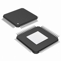
PIC24FJ256DA210T-I/BG Microchip Technology, PIC24FJ256DA210T-I/BG Datasheet - Page 245

PIC24FJ256DA210T-I/BG
Manufacturer Part Number
PIC24FJ256DA210T-I/BG
Description
16-bit, 256KB Flash, 96K RAM, USB, Graphics 121 XBGA 10x10x1.20mm T/R
Manufacturer
Microchip Technology
Series
PIC® 24Fr
Specifications of PIC24FJ256DA210T-I/BG
Core Processor
PIC
Core Size
16-Bit
Speed
32MHz
Connectivity
I²C, IrDA, SPI, UART/USART, USB OTG
Peripherals
Brown-out Detect/Reset, GFX, LVD, POR, PWM, WDT
Number Of I /o
84
Program Memory Size
256KB (85.5K x 24)
Program Memory Type
FLASH
Ram Size
96K x 8
Voltage - Supply (vcc/vdd)
2.2 V ~ 3.6 V
Data Converters
A/D 24x10b
Oscillator Type
Internal
Operating Temperature
-40°C ~ 85°C
Package / Case
121-TFBGA
Lead Free Status / RoHS Status
Lead free / RoHS Compliant
Eeprom Size
-
Lead Free Status / RoHS Status
Lead free / RoHS Compliant
Available stocks
Company
Part Number
Manufacturer
Quantity
Price
Company:
Part Number:
PIC24FJ256DA210T-I/BG
Manufacturer:
Microchip Technology
Quantity:
10 000
- Current page: 245 of 408
- Download datasheet (4Mb)
BDs have a fixed relationship to a particular endpoint,
depending on the buffering configuration. Table 18-2
provides the mapping of BDs to endpoints. This rela-
tionship also means that gaps may occur in the BDT if
endpoints are not enabled contiguously. This, theoreti-
cally, means that the BDs for disabled endpoints could
be used as buffer space. In practice, users should
avoid using such spaces in the BDT unless a method
of validating BD addresses is implemented.
18.2.1
Because the buffers and their BDs are shared between
the CPU and the USB module, a simple semaphore
mechanism is used to distinguish which is allowed to
update the BD and associated buffers in memory. This
is done by using the UOWN bit as a semaphore to
distinguish which is allowed to update the BD and
associated buffers in memory. UOWN is the only bit
that is shared between the two configurations of
BDnSTAT.
When UOWN is clear, the BD entry is “owned” by the
microcontroller core. When the UOWN bit is set, the BD
entry and the buffer memory are “owned” by the USB
peripheral. The core should not modify the BD or its
TABLE 18-2:
2010 Microchip Technology Inc.
Legend:
Endpoint
10
11
12
13
14
15
0
1
2
3
4
5
6
7
8
9
(E) = Even transaction buffer, (O) = Odd transaction buffer
BUFFER OWNERSHIP
(No Ping-Pong)
Out
10
12
14
16
18
20
22
24
26
28
30
0
2
4
6
8
ASSIGNMENT OF BUFFER DESCRIPTORS FOR THE DIFFERENT
BUFFERING MODES
Mode 0
11
13
15
17
19
21
23
25
27
29
31
In
1
3
5
7
9
(Ping-Pong on EP0 OUT)
0 (E), 1 (O)
Out
13
15
17
19
21
23
25
27
29
31
11
3
5
7
9
Mode 1
PIC24FJ256DA210 FAMILY
BDs Assigned to Endpoint
10
12
14
16
18
20
22
24
26
28
30
32
In
2
4
6
8
12 (E), 13 (O)
16 (E), 17 (O)
20 (E), 21 (O)
24 (E), 25 (O)
28 (E), 29 (O)
32 (E), 33 (O)
36 (E), 37 (O)
40 (E), 41 (O)
44 (E), 45 (O)
48 (E), 49 (O)
52 (E), 53 (O)
56 (E), 57 (O)
60 (E), 61 (O)
0 (E), 1 (O)
4 (E), 5 (O)
8 (E), 9 (O)
corresponding data buffer during this time. Note that
the microcontroller core can still read BDnSTAT while
the SIE owns the buffer and vice versa.
The Buffer Descriptors have a different meaning based
on the source of the register update. Register 18-1 and
Register 18-2 show the differences in BDnSTAT
depending on its current “ownership”.
When UOWN is set, the user can no longer depend on
the values that were written to the BDs. From this point,
the USB module updates the BDs as necessary, over-
writing the original BD values. The BDnSTAT register is
updated by the SIE with the token PID and the transfer
count is updated.
18.2.2
The USB OTG module uses a dedicated DMA to
access both the BDT and the endpoint data buffers.
Since part of the address space of the DMA is dedi-
cated to the Buffer Descriptors, a portion of the memory
connected to the DMA must comprise a contiguous
address space properly mapped for the access by the
module.
(Ping-Pong on all EPs)
Out
Mode 2
DMA INTERFACE
14 (E), 15 (O)
18 (E), 19 (O)
22 (E), 23 (O)
26 (E), 27 (O)
34 (E), 35 (O)
38 (E), 39 (O)
42 (E), 43 (O)
46 (E), 47 (O)
50 (E), 51 (O)
54 (E), 55 (O)
58 (E), 59 (O)
62 (E), 63 (O)
10 (E), 11 (O)
30 (E), 31 (O) 26 (E), 27 (O) 28 (E), 29 (O)
2 (E), 3 (O)
6 (E), 7 (O)
In
(Ping-Pong on all other EPs,
10 (E), 11 (O) 12 (E), 13 (O)
14 (E), 15 (O) 16 (E), 17 (O)
18 (E), 19 (O) 20 (E), 21 (O)
22 (E), 23 (O) 24 (E), 25 (O)
34 (E), 35 (O) 36 (E), 37 (O)
38 (E), 39 (O) 40 (E), 41 (O)
42 (E), 43 (O) 44 (E), 45 (O)
46 (E), 47 (O) 48 (E), 49 (O)
50 (E), 51 (O) 52 (E), 53 (O)
54 (E), 55 (O) 56 (E), 57 (O)
58 (E), 59 (O) 60 (E), 61 (O)
30 (E), 31 (O) 32 (E), 33 (O)
2 (E), 3 (O)
6 (E), 7 (O)
Out
0
except EP0)
DS39969B-page 245
Mode 3
4 (E), 5 (O)
8 (E), 9 (O)
In
1
Related parts for PIC24FJ256DA210T-I/BG
Image
Part Number
Description
Manufacturer
Datasheet
Request
R

Part Number:
Description:
Manufacturer:
Microchip Technology Inc.
Datasheet:

Part Number:
Description:
Manufacturer:
Microchip Technology Inc.
Datasheet:

Part Number:
Description:
Manufacturer:
Microchip Technology Inc.
Datasheet:

Part Number:
Description:
Manufacturer:
Microchip Technology Inc.
Datasheet:

Part Number:
Description:
Manufacturer:
Microchip Technology Inc.
Datasheet:

Part Number:
Description:
Manufacturer:
Microchip Technology Inc.
Datasheet:

Part Number:
Description:
Manufacturer:
Microchip Technology Inc.
Datasheet:

Part Number:
Description:
Manufacturer:
Microchip Technology Inc.
Datasheet:


