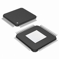
PIC24FJ256DA210T-I/BG Microchip Technology, PIC24FJ256DA210T-I/BG Datasheet - Page 271

PIC24FJ256DA210T-I/BG
Manufacturer Part Number
PIC24FJ256DA210T-I/BG
Description
16-bit, 256KB Flash, 96K RAM, USB, Graphics 121 XBGA 10x10x1.20mm T/R
Manufacturer
Microchip Technology
Series
PIC® 24Fr
Specifications of PIC24FJ256DA210T-I/BG
Core Processor
PIC
Core Size
16-Bit
Speed
32MHz
Connectivity
I²C, IrDA, SPI, UART/USART, USB OTG
Peripherals
Brown-out Detect/Reset, GFX, LVD, POR, PWM, WDT
Number Of I /o
84
Program Memory Size
256KB (85.5K x 24)
Program Memory Type
FLASH
Ram Size
96K x 8
Voltage - Supply (vcc/vdd)
2.2 V ~ 3.6 V
Data Converters
A/D 24x10b
Oscillator Type
Internal
Operating Temperature
-40°C ~ 85°C
Package / Case
121-TFBGA
Lead Free Status / RoHS Status
Lead free / RoHS Compliant
Eeprom Size
-
Lead Free Status / RoHS Status
Lead free / RoHS Compliant
Available stocks
Company
Part Number
Manufacturer
Quantity
Price
Company:
Part Number:
PIC24FJ256DA210T-I/BG
Manufacturer:
Microchip Technology
Quantity:
10 000
- Current page: 271 of 408
- Download datasheet (4Mb)
18.7.3
REGISTER 18-21: U1EPn: USB ENDPOINT n CONTROL REGISTERS (n = 0 TO 15)
2010 Microchip Technology Inc.
bit 15
bit 7
Legend:
R = Readable bit
-n = Value at POR
bit 15-8
bit 7
bit 6
bit 5
bit 4
bit 3
bit 2
bit 1
bit 0
Note 1:
LSPD
R/W-0
U-0
—
(1)
These bits are available only for U1EP0 and only in Host mode. For all other U1EPn registers, these bits
are always unimplemented and read as ‘0’.
USB ENDPOINT MANAGEMENT REGISTERS
RETRYDIS
Unimplemented: Read as ‘0’
LSPD: Low-Speed Direct Connection Enable bit (U1EP0 only)
1 = Direct connection to a low-speed device is enabled
0 = Direct connection to a low-speed device is disabled
RETRYDIS: Retry Disable bit (U1EP0 only)
1 = Retry NAK transactions is disabled
0 = Retry NAK transactions is enabled; retry is done in hardware
Unimplemented: Read as ‘0’
EPCONDIS: Bidirectional Endpoint Control bit
If EPTXEN and EPRXEN = 1:
1 = Disable Endpoint n from control transfers; only TX and RX transfers are allowed
0 = Enable Endpoint n for control (SETUP) transfers; TX and RX transfers are also allowed
For all other combinations of EPTXEN and EPRXEN:
This bit is ignored.
EPRXEN: Endpoint Receive Enable bit
1 = Endpoint n receive is enabled
0 = Endpoint n receive is disabled
EPTXEN: Endpoint Transmit Enable bit
1 = Endpoint n transmit is enabled
0 = Endpoint n transmit is disabled
EPSTALL: Endpoint Stall Status bit
1 = Endpoint n was stalled
0 = Endpoint n was not stalled
EPHSHK: Endpoint Handshake Enable bit
1 = Endpoint handshake is enabled
0 = Endpoint handshake is disabled (typically used for isochronous endpoints)
R/W-0
U-0
—
(1)
W = Writable bit
‘1’ = Bit is set
U-0
U-0
—
—
EPCONDIS
PIC24FJ256DA210 FAMILY
R/W-0
U-0
—
(1)
U = Unimplemented bit, read as ‘0’
‘0’ = Bit is cleared
EPRXEN
R/W-0
U-0
—
EPTXEN
(1)
R/W-0
U-0
—
x = Bit is unknown
EPSTALL
R/W-0
U-0
—
DS39969B-page 271
EPHSHK
R/W-0
U-0
—
bit 8
bit 0
Related parts for PIC24FJ256DA210T-I/BG
Image
Part Number
Description
Manufacturer
Datasheet
Request
R

Part Number:
Description:
Manufacturer:
Microchip Technology Inc.
Datasheet:

Part Number:
Description:
Manufacturer:
Microchip Technology Inc.
Datasheet:

Part Number:
Description:
Manufacturer:
Microchip Technology Inc.
Datasheet:

Part Number:
Description:
Manufacturer:
Microchip Technology Inc.
Datasheet:

Part Number:
Description:
Manufacturer:
Microchip Technology Inc.
Datasheet:

Part Number:
Description:
Manufacturer:
Microchip Technology Inc.
Datasheet:

Part Number:
Description:
Manufacturer:
Microchip Technology Inc.
Datasheet:

Part Number:
Description:
Manufacturer:
Microchip Technology Inc.
Datasheet:


