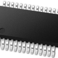
PIC24FJ64GB002-I/SS Microchip Technology, PIC24FJ64GB002-I/SS Datasheet - Page 341

PIC24FJ64GB002-I/SS
Manufacturer Part Number
PIC24FJ64GB002-I/SS
Description
16-bit, 16 MIPS, 64KB Flash, 8KB RAM, Nanowatt XLP, USB OTG 28 SSOP .209in TUBE
Manufacturer
Microchip Technology
Specifications of PIC24FJ64GB002-I/SS
Processor Series
PIC24
Core
PIC24F
Data Bus Width
16 bit
Program Memory Type
Flash
Program Memory Size
64 KB
Data Ram Size
8192 B
Interface Type
I2C, SPI, UART
Maximum Clock Frequency
32 MHz
Number Of Programmable I/os
21
Number Of Timers
5
Operating Supply Voltage
2 V to 3.6 V
Maximum Operating Temperature
+ 85 C
Mounting Style
SMD/SMT
Package / Case
SSOP-28
Development Tools By Supplier
MPLAB Integrated Development Environment
Minimum Operating Temperature
- 40 C
Operating Temperature Range
- 40 C to + 85 C
Supply Current (max)
300 mA
Lead Free Status / Rohs Status
Lead free / RoHS Compliant
Available stocks
Company
Part Number
Manufacturer
Quantity
Price
Part Number:
PIC24FJ64GB002-I/SS
Manufacturer:
MICROCHIP/微芯
Quantity:
20 000
- Current page: 341 of 352
- Download datasheet (3Mb)
APPENDIX A:
Revision A (April 2009)
Original data sheet for the PIC24FJ64GB004 family of
devices.
Revision B (July 2009)
Removed the unimplemented CNPD1 and CNPD2
registers from Table 4-4. Corrected the addresses of
the CNPU1 and CNPU2 registers in the same table.
Updated Table 6-2 (Reset Delay Times) with the
addition of T
Updated Register 7-35 (INTTREG) with a more
descriptive version.
Updated Section 9.2.4 “Deep Sleep Mode” with
family-specific information and an extended discussion
of special cases for Deep Sleep mode entry.
Updated Section 29.1 “DC Characteristics” as
follows:
• Added Maximum values to Tables 29-4, 29-5,
• Updated specifications in Tables 29-3 and 29-8.
• Added new Tables 29-11 (Comparator Specifica-
• Removed redundant or obsolete specifications in
Updated Section 29.2 “AC Characteristics and
Timing Parameters” as follows:
• Updated specifications in Tables 29-17 and
• Added new Table 29-21 (Reset, Power-up Timer
Other minor typographic revisions throughout the
document.
2010 Microchip Technology Inc.
29-6 and 29-7.
tions) and 29-12 (Comparator Voltage Reference
Specifications), renumbering all subsequent
tables.
Tables 29-6, 29-7 and 29-12.
29-19.
and Brown-out Reset Timing Requirements),
renumbering all subsequent tables.
RSRT
to all table entries.
REVISION HISTORY
PIC24FJ64GB004 FAMILY
Revision C (October 2009)
Corrected Section 10.3 “Input Change Notification”
regarding the number of ICN inputs and the availability
of pull-downs.
Updated Section 10.4.2 “Available Peripherals” by
removing the Timer 1 clock input from Table 10-2.
Updated Section 29.1 “DC Characteristics” as
follows:
• Added new specifications to Tables 29-4 and 29-5
• Updated Table 29-4 with revised maximum I
• Renumbered the parameters for the delta I
Revision D (August 2010)
Updated
Peripheral Pin Selection” as follows:
• Replaced the code in Example 10-1.
• Added the new code in Example 10-3.
Updated Figure 18-1 in Section 18.0 “Universal
Serial Bus with On-The-Go Support (USB OTG)”
Updated
follows:
• Added the “125°c data” in
• Updated Min and Typ columns of DC16 in
• Updated OS10 parameter in Table 29-16.
• Added rows, AD08 and AD09, in Table 29-22.
• Added Figure 29-2.
for I
specifications for 1 MIPS and 4 MIPS.
current (32 kHz, SOSCEL = 11) from DC62n to
DC63n.
Table 29-4,Table 29-5,Table 29-6 and Table 29-7.
Table 29-3.
DD
and I
Section 29.1
Section 10.4.5
IDLE
at 0.5 MIPS operation.
“DC
“Considerations
Characteristics”as
PD
DD
for
Related parts for PIC24FJ64GB002-I/SS
Image
Part Number
Description
Manufacturer
Datasheet
Request
R

Part Number:
Description:
Manufacturer:
Microchip Technology Inc.
Datasheet:

Part Number:
Description:
Manufacturer:
Microchip Technology Inc.
Datasheet:

Part Number:
Description:
Manufacturer:
Microchip Technology Inc.
Datasheet:

Part Number:
Description:
Manufacturer:
Microchip Technology Inc.
Datasheet:

Part Number:
Description:
Manufacturer:
Microchip Technology Inc.
Datasheet:

Part Number:
Description:
Manufacturer:
Microchip Technology Inc.
Datasheet:

Part Number:
Description:
Manufacturer:
Microchip Technology Inc.
Datasheet:

Part Number:
Description:
Manufacturer:
Microchip Technology Inc.
Datasheet:


