SM72442X/NOPB National Semiconductor, SM72442X/NOPB Datasheet - Page 4
SM72442X/NOPB
Manufacturer Part Number
SM72442X/NOPB
Description
PV DMPPT Controller - Solar
Manufacturer
National Semiconductor
Series
SolarMagic™r
Datasheet
1.SM72442ENOPB.pdf
(14 pages)
Specifications of SM72442X/NOPB
Applications
Controller, Pholovoltaic Solar Panels
Voltage - Input
4.75 V ~ 5.25 V
Number Of Outputs
4
Voltage - Output
-
Operating Temperature
-40°C ~ 105°C
Mounting Type
Surface Mount
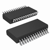
Package / Case
28-TSSOP (0.173", 4.40mm Width)
Lead Free Status / Rohs Status
Lead free / RoHS Compliant


www.national.com
Pin
Pin Descriptions
10
11
12
13
14
15
16
17
18
19
20
21
22
23
24
25
26
27
28
1
2
3
4
5
6
7
8
9
PM_OUT When Panel Mode is active, this pin will output a 400 kHz square wave signal with amplitude of 5V. Otherwise, it
AVOUT
AIOUT
VDDD
VDDA
Name
VSSD
VSSA
AVIN
I2C0
I2C1
I2C2
RST
NC1
NC2
SCL
SDA
NC3
AIIN
NC4
HIB
HIA
LIB
LIA
PM
A0
A2
A4
A6
Description
Active low signal. External reset input signal to the digital circuit.
Reserved for test only. This pin should be grounded.
Digital supply voltage. This pin should be connected to a 5V supply, and bypassed to VSSD with a 0.1 µF monolithic
ceramic capacitor.
Digital ground. The ground return for the digital supply and signals.
No Connect. This pin should be pulled up to the 5V supply using 10k resistor.
Addressing for I2C communication.
Addressing for I2C communication.
I2C clock.
I2C data.
Reserved for test only. This pin should be grounded.
stays low.
Analog supply voltage. This voltage is also used as the reference voltage. This pin should be connected to a 5V
supply, and bypassed to VSSA with a 1 µF and 0.1 µF monolithic ceramic capacitor.
Analog ground. The ground return for the analog supply and signals.
A/D Input Channel 0. Connect a resistor divider to 5V supply to set the maximum output voltage. Please refer to
the application section for more information on setting the resistor value.
Input voltage sensing pin.
A/D Input Channel 2. Connect a resistor divider to a 5V supply to set the condition to enter and exit Panel Mode
(PM). Refer to configurable modes for SM72442 in the application section.
Output voltage sensing pin.
A/D Input Channel 4. Connect a resistor divider to a 5V supply to set the maximum output current. Please refer to
the application section for more information on setting the resistor value.
Input current sensing pin.
A/D Input Channel 6. Connect a resistor divider to a 5V supply to set the output voltage slew rate and various PM
configurations. Refer to configurable modes for SM72442 in the application section.
Output current sensing pin.
Addressing for I2C communication.
No Connect. This pin should be connected with 60.4k pull-up resistor to 5V.
Low side boost PWM output.
High side boost PWM output.
High side buck PWM output.
Low side buck PWM output.
Panel Mode Pin. Active low. Pulling this pin low will force the chip into Panel Mode.
4
Related parts for SM72442X/NOPB
Image
Part Number
Description
Manufacturer
Datasheet
Request
R

Part Number:
Description:
PV DMPPT Controller - Solar
Manufacturer:
National Semiconductor
Datasheet:

Part Number:
Description:
SILICON GATE ENHANCEMENT MODE RF POWER VDMOS TRANSISTOR
Manufacturer:
POLYFET [Polyfet RF Devices]
Datasheet:

Part Number:
Description:
National Semiconductor [8-Bit D/A Converter]
Manufacturer:
National Semiconductor
Datasheet:
Part Number:
Description:
National Semiconductor [Media Coprocessor]
Manufacturer:
National Semiconductor
Datasheet:
Part Number:
Description:
Digitally Controlled Tone and Volume Circuit with Stereo Audio Power Amplifier, Microphone Preamp Stage and National 3D Sound
Manufacturer:
National Semiconductor
Datasheet:
Part Number:
Description:
Digitally Controlled Tone and Volume Circuit with Stereo Audio Power Amplifier, Microphone Preamp Stage and National 3D Sound
Manufacturer:
National Semiconductor
Datasheet:
Part Number:
Description:
AC97 Rev 2 Codec with Sample Rate Conversion and National 3D Sound
Manufacturer:
National Semiconductor
Part Number:
Description:
Manufacturer:
National Semiconductor
Datasheet:
Part Number:
Description:
Manufacturer:
National Semiconductor
Datasheet:
Part Number:
Description:
General Purpose, Low Voltage, Low Power, Rail-to-Rail Output Operational Amplifiers
Manufacturer:
National Semiconductor
Datasheet:
Part Number:
Description:
8-bit 20 MSPS flash A/D converter.
Manufacturer:
National Semiconductor
Datasheet:
Part Number:
Description:
Low Noise Quad Operational Amplifier
Manufacturer:
National Semiconductor
Datasheet:
Part Number:
Description:
Quad Differential Line Receivers
Manufacturer:
National Semiconductor
Datasheet: