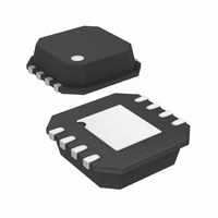
SSM2211CPZ-R2 Analog Devices Inc, SSM2211CPZ-R2 Datasheet - Page 5

SSM2211CPZ-R2
Manufacturer Part Number
SSM2211CPZ-R2
Description
IC,Audio Amplifier,SINGLE,CMOS,LLCC,8PIN,PLASTIC
Manufacturer
Analog Devices Inc
Type
Class ABr
Datasheet
1.SSM2211SZ.pdf
(24 pages)
Specifications of SSM2211CPZ-R2
Output Type
1-Channel (Mono)
Max Output Power X Channels @ Load
1.5W x 1 @ 4 Ohm
Voltage - Supply
2.7 V ~ 5.5 V
Features
Differential Inputs, Shutdown
Mounting Type
Surface Mount
Package / Case
8-LFCSP
Operational Class
Class-AB
Audio Amplifier Output Configuration
1-Channel Mono
Audio Amplifier Function
Speaker
Total Harmonic Distortion
0.2%%
Single Supply Voltage (typ)
3/5V
Dual Supply Voltage (typ)
Not RequiredV
Supply Current (max)
20@5V@-40C TO 85CmA
Power Supply Requirement
Single
Unity Gain Bandwidth Product (typ)
4MHz
Rail/rail I/o Type
Rail to Rail Input
Power Supply Rejection Ratio
66dB
Single Supply Voltage (min)
2.7V
Single Supply Voltage (max)
5.5V
Dual Supply Voltage (min)
Not RequiredV
Dual Supply Voltage (max)
Not RequiredV
Operating Temp Range
-40C to 85C
Operating Temperature Classification
Industrial
Mounting
Surface Mount
Pin Count
8
Package Type
LFCSP EP
Lead Free Status / RoHS Status
Lead free / RoHS Compliant
Lead Free Status / RoHS Status
Lead free / RoHS Compliant
ABSOLUTE MAXIMUM RATINGS
Absolute maximum ratings apply at T
otherwise noted.
Table 4.
Parameter
Supply Voltage
Input Voltage
Common-Mode Input Voltage
ESD Susceptibility
Storage Temperature Range
Operating Temperature Range
Junction Temperature Range
Lead Temperature, Soldering (60 sec)
Stresses above those listed under Absolute Maximum Ratings
may cause permanent damage to the device. This is a stress
rating only; functional operation of the device at these or any
other conditions above those indicated in the operational
section of this specification is not implied. Exposure to absolute
maximum rating conditions for extended periods may affect
device reliability.
A
= 25°C, unless
Rating
6 V
V
V
2000 V
−65°C to +150°C
−40°C to +85°C
−65°C to +165°C
300°C
DD
DD
Rev. E | Page 5 of 24
THERMAL RESISTANCE
θ
soldered in a circuit board for surface-mount packages.
Table 5. Thermal Resistance
Package Type
8-Lead LFCSP_VD (CP-Suffix)
8-Lead SOIC_N (S-Suffix)
1
2
ESD CAUTION
For the LFCSP_VD, θ
For the SOIC_N, θ
JA
is specified for the worst-case conditions, that is, a device
JA
JA
is measured with the device soldered to a four-layer PCB.
is measured with exposed lead frame soldered to the PCB.
2
1
θ
50
121
JA
SSM2211
Unit
°C/W
°C/W


