SSM2311CBZ-REEL7 Analog Devices Inc, SSM2311CBZ-REEL7 Datasheet
SSM2311CBZ-REEL7
Specifications of SSM2311CBZ-REEL7


Related parts for SSM2311CBZ-REEL7


SSM2311CBZ-REEL7 Summary of contents
Page 1
FEATURES Filterless Class-D amplifier with Σ-Δ modulation No sync necessary when using multiple Analog Devices, Inc., Class-D amplifiers 3 W into 3 Ω load and 1.4 W into 8 Ω load at 5.0 V supply with less than 10% total ...
Page 2
SSM2311 TABLE OF CONTENTS Features .............................................................................................. 1 Applications....................................................................................... 1 General Description ......................................................................... 1 Functional Block Diagram .............................................................. 1 Revision History ............................................................................... 2 Specifications..................................................................................... 3 Absolute Maximum Ratings............................................................ 4 Thermal Resistance ...................................................................... 4 ESD Caution.................................................................................. 4 Pin Configuration and Function Descriptions............................. ...
Page 3
SPECIFICATIONS 5 Ω, unless otherwise noted Table 1. Parameter DEVICE CHARACTERISTICS Output Power Efficiency Total Harmonic Distortion + Noise Input Common-Mode Voltage Range Common-Mode Rejection Ratio ...
Page 4
SSM2311 ABSOLUTE MAXIMUM RATINGS Absolute maximum ratings apply at 25°C, unless otherwise noted. Table 2. Parameter Supply Voltage Input Voltage Common-Mode Input Voltage Storage Temperature Range Operating Temperature Range Junction Temperature Range Lead Temperature (Soldering, 60 sec) Stresses above those ...
Page 5
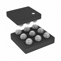
PIN CONFIGURATION AND FUNCTION DESCRIPTIONS Table 4. Pin Function Descriptions Pin No. Mnemonic IN+ 1C IN− 3C OUT− 1B VDD 2A, 3B GND 3A OUT+ 2B PVDD BALL A1 CORNER SSM2311 ...
Page 6
SSM2311 TYPICAL PERFORMANCE CHARACTERISTICS 100 R = 8Ω, 33µH L GAIN = 18dB 0 3.6V DD 0.01 0.001 0.0001 0.001 0.01 0.1 OUTPUT POWER (W) Figure 3. THD + N vs. Output Power into ...
Page 7
GAIN = 18dB R = 8Ω, 33µ 0.1 0.5W 0.01 0.25W 0.001 10 100 1k 10k FREQUENCY (Hz) Figure 9. THD + N vs. Frequency 5 ...
Page 8
SSM2311 100 V = 2.5V DD GAIN = 18dB R = 8Ω, 33µ 0.1 0.125W 0.01 0.075W 0.001 10 100 1k FREQUENCY (Hz) Figure 15. THD + N vs. Frequency 2 100 ...
Page 9
GAIN = 18dB 3 4Ω, 33µH L 2.5 10% 2.0 1.5 1.0 0.5 0 2.5 3.0 3.5 4.0 SUPPLY VOLTAGE (V) Figure 21. Maximum Output Power vs. Supply Voltage 1kHz ...
Page 10
SSM2311 100 0.2 0.4 0.6 0.8 1.0 1.2 1.4 OUTPUT POWER (W) Figure 27. Efficiency vs. Output Power into 4 Ω ...
Page 11
V = 3. 4Ω, 33µH L 0.20 0.18 0.16 0.14 0.12 0.10 0.08 0.06 0.04 0. 0.1 0.2 0.3 0.4 0.5 0.6 0.7 0.8 0.9 1.0 1.1 1.2 1.3 1.4 1.5 1.6 OUTPUT ...
Page 12
SSM2311 8Ω, 33µH L –10 –20 –30 –40 –50 –60 –70 –80 10 100 1k FREQUENCY (Hz) Figure 39. Common-Mode Rejection Ratio vs. Frequency 3. rms RIPPLE – ...
Page 13
TYPICAL APPLICATION CIRCUITS 22nF AUDIO IN+ AUDIO IN– 22nF SHUTDOWN AUDIO IN+ SHUTDOWN 10µF 0.1µF 300kΩ SSM2311 1 37.5kΩ IN+ MODULATOR IN– 37.5kΩ 1 300kΩ SD BIAS OSCILLATOR 1 INPUT CAPS ARE OPTIONAL IF INPUT DC COMMON-MODE VOLTAGE IS APPROXIMATELY ...
Page 14
SSM2311 22nF AUDIO IN+ AUDIO IN– 22nF SHUTDOWN 300kΩ GAIN = (37.5kΩ 22nF AUDIO IN+ 22nF SHUTDOWN 300kΩ GAIN = (37.5kΩ 10µF 0.1µF 300kΩ SSM2311 1 R 37.5kΩ IN+ EXT MODULATOR IN– R 37.5kΩ 1 EXT ...
Page 15
APPLICATION NOTES OVERVIEW The SSM2311 mono Class-D audio amplifier features a filterless modulation scheme that greatly reduces the external components count, conserving board space and thus reducing the system’s cost. The SSM2311 does not require an output filter, but instead ...
Page 16
SSM2311 INPUT CAPACITOR SELECTION The SSM2311 does not require input coupling capacitors if the input signal is biased from 1 − 1.0 V. Input capacitors DD are required if the input signal is not biased within this ...
Page 17
... OUTLINE DIMENSIONS BALL 1 IDENTIFIER (BALL SIDE DOWN) ORDERING GUIDE Model Temperature Range 1 SSM2311CBZ-R2 −40°C to +85°C SSM2311CBZ-REEL 1 −40°C to +85°C 1 SSM2311CBZ-REEL7 −40°C to +85°C SSM2311-EVALZ 1 1 SSM2311-MINI-EVALZ RoHS Compliant Part. 0.65 0.59 1.575 0.53 1.515 SEATING 1.455 PLANE ...
Page 18
SSM2311 NOTES Rev Page ...
Page 19
NOTES Rev Page SSM2311 ...
Page 20
SSM2311 NOTES ©2008 Analog Devices, Inc. All rights reserved. Trademarks and registered trademarks are the property of their respective owners. D06161-0-1/08(0) Rev Page ...