ACV12012 PANASONIC EW, ACV12012 Datasheet
ACV12012
Specifications of ACV12012


Related parts for ACV12012


ACV12012 Summary of contents
Page 1
CV (ACV 22.5 .591 .886 15.7 .618 Micro ISO 1c type Micro ISO 1a type 22.5 .886 Micro 280 plug-in type Micro 280 PCB type RoHS Directive compatibility information http://www.nais-e.com/ SPECIFICATIONS Contact Arrangement 1 Form A Contact material ...
Page 2
... Schematic (Bottom view) 1 Form Including diode type, including resistor type also available 1 Form C 2 Tolerance 4 0.1 .004 1 inch: 0.2 .008 Including diode type, including resistor type also available 0.3 .012 CV (ACV) Part No. ACV31012 ACV32012 ACV33012 ACV11012 ACV12012 ACV13012 Usable voltage range ( 185 inch ...
Page 3
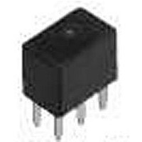
CV (ACV) 2. Micro 280 terminal type 1). Plug-in type 7.8 .307 Sealed by epoxy resin * Intervals between terminals is measured at A surface level. 2). PC board type 16.7 1 .657 .039 3.5 .138 *A 7.8 .307 Sealed ...
Page 4
Electrical life test (Resistive load) Sample: ACV12212, 3pcs. Load: Resistive load (NC switching) 11A Switching frequency: (ON : OFF = 1s : 1s) Ambient temperature: Room temperature Circuit 13.5VDC Load current waveform Up: Coil Down: Load 10V 5A voltage ...
Page 5
CV (ACV) 4-(3). Electrical life test (Motor load) Sample: ACV12212, 3pcs. Load: inrush: 80A/steady: 18A, radiator fan actual load (motor free) Switching frequency: (ON : OFF = 2s : 6s) Ambient temperature: Room temperature Circuit M M 13.5VDC Load current ...