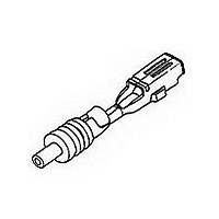
171662-1 TE Connectivity, 171662-1 Datasheet - Page 32

171662-1
Manufacturer Part Number
171662-1
Description
E-J MK-2 070 REC CONT
Manufacturer
TE Connectivity
Type
Contactr
Series
070r
Datasheet
1.171662-1.pdf
(80 pages)
Specifications of 171662-1
Gender
RCP
Body Orientation
Straight
Housing Material
Not Required
Number Of Contacts
1POS
Number Of Ports
1Port
Number Of Terminals
1
Pitch (mm)
Not Requiredmm
Contact Material
Brass
Operating Temp Range
-30C to 105C
Mounting Style
Cable
Termination Method
Crimp
Contact Plating
Pre-Tin
Product Height (mm)
3.6mm
Product Depth (mm)
5.4mm
Product Length (mm)
16.5mm
Product Line
Econoseal J
Product Type
Contact
Wire/cable Type
Discrete Wire
Cable Type
Thin Wall
Termination Method To Wire/cable
Crimp
Wire/cable Size (awg)
16 – 20
Wire/cable Size (mm²)
0.5 – 1.25
Wire Type
Stranded
Contact Type
Socket
Contact Base Material
Brass
Contact Plating, Mating Area, Material
Pre-Tin
Contact Plating, Mating Area, Thickness (µm [?in])
0.76 [29.92]
Rohs/elv Compliance
RoHS compliant, ELV compliant
Lead Free Solder Processes
Not relevant for lead free process
Rohs/elv Compliance History
Always was RoHS compliant
Applies To
Wire/Cable
Accepts Wire Insulation Diameter, Range (mm [in])
2.00 – 2.60 [0.079 – 0.102]
Application Use
Wire-to-Wire
Contact Transmits (typical Application)
Power
Packaging Method
Reel
Packaging Quantity
6000
Lead Free Status / RoHS Status
Compliant
Available stocks
Company
Part Number
Manufacturer
Quantity
Price
Company:
Part Number:
171662-1
Manufacturer:
TE/AMP
Quantity:
30 000
Company:
Part Number:
171662-1
Manufacturer:
TE/TYCO
Quantity:
6 600
32
AMP Sealed Connectors
A
Contacts
Wire Seals
Connector Housings
Available in 1.5 mm [.059 in.]
and 2.5 mm [.098 in. ] pin
diameters.
Available with either tin,
silver or gold plating.
Rugged two piece
construction with stainless
steel jacket allows the use
of optimized (CuNiSi)
contact material.
Six points of contact (2.5 mm
System) and five points of
contact (1.5 mm System)
2.5 mm System wire range
0.2 - 2.5 mm
AWG.
1.5 mm System wire range
0.2 - 2.5 mm
AWG.
Made from silicon rubber
material.
Wire seal is crimped
simultaneously with the
contact.
2.5 mm System accomodates
insulation diameters of
1.2 - 3.0 mm [.047 - .118 in.].
1.5 mm System accomodates
insulation diameters of
1.2 - 3.0 mm [.047 - .118 in.]
Made from glass filled PBT
material.
2.5 mm System will mate to
customer interfaces made
per DIN 72585.
Pre-assembled interface
and panel mounting seal.
The 2.5 mm System is
available in 4 position or in
2 and 3 positions with
blocked cavities. Four
keying options are
available per position size.
The 1.5 mm System is
available only in a 7
position version.
2
2
[#24 - #14]
[#24 - #14]
AMP Technical Support Center/AMP FAX Service
1-800-522-6752 717-986-7777
AMP Sealed Connectors
Sealed Circular Connectors . . . 2.5mm and 1.5mm Systems
AMP in conjunction with
major European truck
manufacturers has
developed a standard
system of circular sealed
connectors to meet the
demand for superior
performance under
environments of extreme
vibration, physical shock
and temperature change.
Typical applications include
magnetic valves, sensors
for ABS and powertrain
management (including
direct engine mounting)
and lighting.
The 2.5 mm System uses a
standard outer shell which
can be supplied in either
2 or 3 position versions with
the extra cavities blocked
or in a 4 position version.
Each position size is
available with four different
keying options that are
designated by color code.
The 1.5 mm System uses
the same outer shell but is
available only in a 7
position version.
The shell standardization
allows the use of the same
back shells for all parts.
Back shells are available in
90° and 180° wire exit
versions with the options for
mounting 8.5 mm or 10 mm
convoluted tubing or the
use of our adjustable strain
relief feature on the free
wire version.
The housings are available
as free hanging male and
female connectors or for
mating to a customer
supplied pin interface
according to DIN 72585,
Part 1 (ISO 15170
pending). The free hanging
pin housing is also suitable
for through panel mounting
and is supplied with a pre-
assembled seal for panel
sealing. The actual
mounting is achieved with
the use of a separately
available locking ring.
Terminal construction is
of a two piece design to
allow optimization of
electrical and mechanical
performance. An outer
stainless steel jacket pro-
vide protection against
handling damage.
Dimensions are in
millimeters over [inches]
www.amp.com
Product Performance
Temperature Rating
For tin plating -40° to 130° C
For silver plating -40° to 140° C
For gold plating -40° to 150° C
Dielectric Strength
1.0 kVAC between adjacent contact or to
shell
Contact Termination Resistance
5 m Max. (Initial)
10 m Max. (Final)
Current Guidelines (Map Wire Size)
2.5 mm . . . 30 amps Max.
1.5 mm . . . 25 amps Max.
(Using the maximum wire size at 23°C)
Product Documentation
Product Specification
108-18621
108-18027, DIN 72585 (2.5 mm)
108-18028 (1.5 mm)
Application Specification
114-18255
114-18020 (2.5 mm)
114-18040 (1.5 mm)
Specifications
subject to change.
Revised 01-00
Catalog
65481


