H7BR-CWV-AC100-240 Omron, H7BR-CWV-AC100-240 Datasheet - Page 23
H7BR-CWV-AC100-240
Manufacturer Part Number
H7BR-CWV-AC100-240
Description
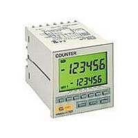
COUNTER DIGITAL LCD 100-240V NPN
Manufacturer
Omron
Series
H7BRr
Type
Digital Counterr
Specifications of H7BR-CWV-AC100-240
Count Rate
*
Number Of Digits/alpha
6
Input Type
*
Output Type
*
Voltage - Supply
100 V ~ 240 VAC
Display Type
*
Equipment Type
Digital Counter
Lead Free Status / RoHS Status
Lead free / RoHS Compliant
Other names
H7BRCWVAC100240


H7BR
Precautions
•
•
•
•
Any changes in the DIP switch settings while power is being sup-
plied is invalid. Restart the power supply.
Power
supply
Input
Sensor Power Supply
Power Supplies
DIP Switch Setting Changes
The capacity of the external power supply is 160 mA at 12
VDC/80 mA at 24 VDC switchable. When using a 24 VAC/12 to
24 VDC power supply type H7BR, reduce the load with the
power supply voltage, as shown in the following diagram (When
supplying external power).
When turning the power ON and OFF, input signal reception is
possible, unstable, or impossible as shown in the diagram below.
The unstable period will vary with power supply voltage, and the
load conditions on external power supplies.
A switching regulator is used in the internal circuits of counters
with 100-to-240-VAC or 12-to-24-VAC specifications, causing
an inrush current (approx. 1.5 A) to flow when power is turned on.
If the capacity of the power supply to the counter is insufficient,
the counter may not start operation. Be sure to provide adequate
capacity (recommended supply capacity; 25 W min.)
Connect the power supply voltage through a relay or switch in
such a way that the voltage reaches a fixed value immediately.
160
80
20
10
0
OFF
ON
0 to 50 ms
impossible
10
Supply voltage (VDC)
17
Possible
10 ms
Unstable
20
impossible
0 to 1.2 s
25
12 VDC
24 VDC
•
*Displayed when the present value has fallen below the min. value
in the H7BR-C (±range type).
**Displayed when the present value has exceeded the max. value in
the H7BR-C (±range type).
•
•
•
•
•
•
Display
Self-diagnostic Function
Operating Environment
Using the Prescale Function
Changing Set Values
Resetting with a Set Value of 0
The following displays will appear if an error occurs. The present
value and output enter the same status as after pressing the
RESET Key.
When using the Counter in an area with much electronic noise,
separate the Timer, wiring, and the equipment which generates
the input signals as far as possible from the noise sources. It is
also recommended to shield the input signal wiring to prevent
electronic interference.
Organic solvents (such as paint thinner), as well as very acidic or
basic solutions might damage the outer casing of the Counter.
When setting the prescale value, be sure that the set value
satisfies this equation: set value “max. value - prescale value’. (if
the prescale value is 1,250, 999.999 - 1,250 = 998.749 max.)
If a higher value is used, the output may be affected, so make
sure that the output is produced before starting operation.
When changing the set value while the Counter is operating, the
output will be produced if the set value ever equals the present
value. To avoid triggering the output, begin by incrementing a
higher digit to a large number.
When resetting is performed with the set value set to “0,” no
output will be given for the safety reasons once the reset is
turned OFF (except for the H7BR-C).
*
**
Present
value
below min.
Present
value
above max.
CPU
Memory
Error
No
change
OFF
Output
status
Press
RESET Key
or reset
input
Press
RESET Key
Correction
No
change
Set at the
factory
Function
setting
H7BR
23