H7BR-CWV-AC100-240 Omron, H7BR-CWV-AC100-240 Datasheet - Page 4
H7BR-CWV-AC100-240
Manufacturer Part Number
H7BR-CWV-AC100-240
Description
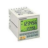
COUNTER DIGITAL LCD 100-240V NPN
Manufacturer
Omron
Series
H7BRr
Type
Digital Counterr
Specifications of H7BR-CWV-AC100-240
Count Rate
*
Number Of Digits/alpha
6
Input Type
*
Output Type
*
Voltage - Supply
100 V ~ 240 VAC
Display Type
*
Equipment Type
Digital Counter
Lead Free Status / RoHS Status
Lead free / RoHS Compliant
Other names
H7BRCWVAC100240


H7BR
*When power is turned ON, approx. 8 A inrush current flows for about 2 ms. (24 VDC, 240 VAC)
4
Rated supply voltage
Operating voltage range
Current consumption
Max. counting speeds (CP1, CP2)
Compensation and gate input
Reset
Batch count reset
Key protection
One-shot time
Count, compensation, reset, batch
count reset, and gate inputs
Key protection input
Control outputs
External power supply
Insulation resistance
Dielectric strength
Impulse withstand voltage
Noise immunity
Static immunity
Vibration resistance
Shock resistance
Life expectancy
Weight
Ambient temperature
Ambient humidity
EMC
Case color
Ratings
Characteristics
100 MΩ min. (at 500 VDC) (between current-carrying terminal and exposed non-current-carrying metal
parts, and between non-continuous contacts)
2,000 VAC, 50/60 Hz for 1 min (between current-carrying terminal and exposed non-current-carrying
metal parts)
3 kV (between power terminals) for 100 to 240 VAC type, 1 kV for 24 VAC/12 to 24 VDC
4.5 kV (between current-carrying terminal and exposed non-current-carrying metal parts for 100 to 240
VAC type, 1.5 kV for 24 VAC/12 to 24 VDC.
±2 kV (between power terminals) and ±600 V (between input terminals), square-wave noise by noise
simulator (pulse width: 100 ns/1 µs, 1-ns rise)
Malfunction: 8 kV; destruction: 15 kV
10 to 55 Hz with 0.75-mm single amplitude each in three directions
10 t 55 H
10 to 55 Hz with 0.5-mm single amplitude each in three directions
300 m/s
300 m/s (Approx. 30G) each in three directions
100 m/s
10 million operations min.
100 000
100,000 operations min. 5 A at 250 VAC in load resistance)
Approx. 270 g
Operating: –10°C to 55°C (with no icing)
Storage: –25°C to 65°C (with no icing)
Operating: 35% to 85%
(EMI):
Emission Enclosure:
Emission AC Mains:
(EMS):
Immunity ESD:
Immunity RF-interference:
Immunity Conducted Disturbance:
Immunity Burst:
Light gray (Munsell 5Y7/1)
2
2
2
100 to 240 VAC, 50/60 Hz
24 VAC/12 to 24 VDC (contains 20% ripple max.)
85% to 110% of rated voltage
Approx. 10 VA at 50 Hz, 240 VAC; approx. 6 W at 24 VDC *
30/1k/5k/10 kcps (separate setting for CP1 and CP2)
Set to the faster of the CP1 and CP2 max. counting speeds
Min. pulse width for external reset: 1 or 20 ms, also manual reset
Min. pulse width: Approx. 20 ms
Response time: 1 s
10, 50, 100, 200, 500, and 1,000 ms (separate setting for stages 1 and 2)
No-voltage input
ON impedance:
ON residual voltage: 2 V max.
OFF impedance:
Voltage input (input resistance: approx. 4.7 kΩ)
High level:
Low level:
No-voltage input
ON impedance:
ON residual voltage: 1 V max.
OFF impedance:
Contacts: 3 A at 250 VAC, resistive load (cos
Transistor output: Open collector 100mA at 30 VDC max. residual voltage 2 V max. (Approx.
1 V)
160 mA, 12 VDC ±10% (5% ripple max.)
80 mA, 24 VDC ±10% (5% ripple max.)
(Approx. 30G) each in three directions
(Approx. 10G) each in three directions
p
ith 0 5
ti
i
5 A t 250 VAC i l
i
1 kΩ max. (Approx. 2 mA when 0 kΩ)
100 kΩ max.
4.5 to 30 VDC
0 to 2 VDC
g
l
1 kΩ max. (Approx. 2 mA when 0 kΩ)
100 kΩ min.
p
lit d
EN50081-2
EN55011 Group 1 class A
EN55011 Group 1 class A
EN50082-2
EN61000-4-2:4 kV contact discharge
ENV50140:
ENV50141:
EN61000-4-4:2 kV power-line
h i th
d
8 kV air discharge
10 V/m (Amplitude-modulated, 80 MHz to 1 GHz)
10 V/m (Pulse-modulated, 900 MHz)
10 V (0.15 to 80 MHz)
2 kV I/O signal-line
i t
φ
di
= 1)
)
ti
H7BR