H7BR-CWV-AC100-240 Omron, H7BR-CWV-AC100-240 Datasheet - Page 5
H7BR-CWV-AC100-240
Manufacturer Part Number
H7BR-CWV-AC100-240
Description
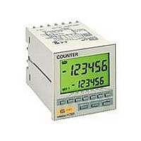
COUNTER DIGITAL LCD 100-240V NPN
Manufacturer
Omron
Series
H7BRr
Type
Digital Counterr
Specifications of H7BR-CWV-AC100-240
Count Rate
*
Number Of Digits/alpha
6
Input Type
*
Output Type
*
Voltage - Supply
100 V ~ 240 VAC
Display Type
*
Equipment Type
Digital Counter
Lead Free Status / RoHS Status
Lead free / RoHS Compliant
Other names
H7BRCWVAC100240


H7BR
Inputs
Outputs
Block Diagram
I/O Functions
* Power supply is insulated from I/O.
External power supply
AC (DC) input
Input circuits
(CP1, CP2, com-
pensation, gate,
reset, batch count
reset, key protec-
tion)
Key switch circuits
CP1/CP2
Reset
Compensation input
(±Range type)
Batch count reset
(Standard type)
Key protection
Gate
OUT 1.2
Batch output
(Standard type)
Function setting
circuit
LCD drive
clock generator
Power circuits *
Count signal inputs.
Up, Down, and Up/Down (command, individual, or quadrature) inputs accepted.
Resets present value. (to zero in Up modes, to preset with 1-stage models in Down mode, and
to preset with 2-stage models.)
Count inputs are not accepted while reset input is ON.
Reset indicator lit while reset input is ON.
On rising edge of up count signal, present count is reset to compensation value and, therefore,
count inputs are accepted even if the compensation input is set to ON (not effective for down
count signals.)
Resets batch count to zero and batch output turns OFF.
Signals are taken in on the ON edge.
Batch count signals are not accepted while batch count reset is ON.
Makes keys inoperative according to key protection level.
Key protection indicator lit while key protection input is ON.
Effective when power supply is turned off.
Effective when protect terminals are shorted.
Inhibits counter operation when gate input is ON.
Outputs made according to designated output mode when corresponding preset is reached.
Outputs inhibit on the teaching mode.
Outputs made when batch counter is up to preset number of batches.
Batch output remains ON until batch count reset goes ON.
When the number of batches is set to zero, batch counting is performed but batch outputs are
not made.
Batch counter counts the number of completed counts to the preset for 1-stage models and to
preset 2 for 2-stage models.
Count
circuits
ROM
System clock
generator
Battery
Control
circuits
RAM
Power outage
detector
One-chip
microcom-
puter
LCD driver
LCD reference
voltage generator
No-contact outputs
inverter (DIP switch
pins 1,2)
Output circuits
(OUT, batch output)
LCD
H7BR
5