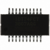
IDT74FCT3807AQG IDT, Integrated Device Technology Inc, IDT74FCT3807AQG Datasheet - Page 6

IDT74FCT3807AQG
Manufacturer Part Number
IDT74FCT3807AQG
Description
IC CLK FAN BUFF 1:10 20QSOP
Manufacturer
IDT, Integrated Device Technology Inc
Series
74FCTr
Type
Fanout Buffer (Distribution)r
Datasheet
1.IDT74FCT3807AQG8.pdf
(8 pages)
Specifications of IDT74FCT3807AQG
Number Of Circuits
1
Ratio - Input:output
1:10
Differential - Input:output
No/No
Input
LVTTL
Output
CMOS, TTL
Frequency - Max
100MHz
Voltage - Supply
3 V ~ 3.6 V
Operating Temperature
0°C ~ 70°C
Mounting Type
Surface Mount
Package / Case
20-QSOP
Frequency-max
100MHz
Number Of Outputs
10
Operating Supply Voltage (max)
3.6V
Operating Temp Range
0C to 70C
Propagation Delay Time
4.3ns
Operating Supply Voltage (min)
3V
Mounting
Surface Mount
Pin Count
20
Operating Supply Voltage (typ)
3.3V
Package Type
QSOP
Quiescent Current
10uA
Input Frequency
133MHz
Operating Temperature Classification
Commercial
Lead Free Status / RoHS Status
Lead free / RoHS Compliant
Other names
74FCT3807AQG
800-1631
800-1631-5
800-1631
800-1631
800-1631-5
800-1631
Available stocks
Company
Part Number
Manufacturer
Quantity
Price
Part Number:
IDT74FCT3807AQG
Manufacturer:
IDT
Quantity:
20 000
Company:
Part Number:
IDT74FCT3807AQG8
Manufacturer:
IDT10
Quantity:
1 938
Part Number:
IDT74FCT3807AQGI
Manufacturer:
IDT
Quantity:
20 000
TEST CIRCUITS
IDT74FCT3807/A
3.3V CMOS 1-TO-10 CLOCK DRIVER
Generator
Generator
Pulse
Pulse
Generator
Pulse
Figure 5. Enable and Disable Time Circuit
Figure 1. Z
V
V
IN
IN
Figure 3. C
V
IN
O
R
= 50 Ω Ω Ω Ω Ω to V
R
T
T
R
D.U.T.
D.U.T.
L
V
T
V
CC
= 30pF Circuit
CC
D.U.T.
V
CC
CC
/2, C
V
OUT
V
OUT
L
= 10pF
V
100
OUT
50pF
C
V
L
CC
100
30pF
C
L
500
500
10pF
6V
GND
6
The capacitor value for ac termination is determined by the operating frequency. For very
low frequencies a higher capacitor value should be selected.
ENABLE AND DISABLE TIME
SWITCH POSITION
DEFINITIONS:
C
R
Generator
L
T
=
=
Pulse
Generator
Load capacitance: includes jig and probe capacitance.
Termination resistance: should be equal to Z
Pulse
Disable HIGH
Enable HIGH
Figure 2. Z
Disable LOW
Enable LOW
COMMERCIAL/INDUSTRIAL TEMPERATURE RANGES
Test
V
IN
V
Figure 3. C
IN
O
= 50 Ω Ω Ω Ω Ω AC Termination, C
R
T
R
D.U.T.
T
V
L
CC
= 50pF Circuit
D.U.T.
V
CC
OUT
V
of the Pulse Generator.
OUT
V
Switch
OUT
220pF
GND
L
50
6V
= 10pF
50pF
C
L
10pF


